Gates Radio M-5078 Commercial SW AM/CW Transmitter
Restoration Details - Part Eight
Electronics Evaluation, Testing & Restoration Continued.
Dated: July 20, 2012
Redesigned PTT Circuit
I would like to describe the reworking I have done to the the PTT circuit for this radio. As previously mentioned the radio orginally only had the capability of switching the internal antenna changover relay by turning on or off the high voltage switch on the front panel. The microphone switch only makes or breaks the audio signal coming from the mic. A previous owner of this radio added an adhoc full PTT function. This included some wiring, a relay and powering transformer, and replacing the two contact mic input connector (signal & ground) with a three contact mic connector (signal, PTT & ground).
It appears many of these components were taken from a "junk box". The wiring was also done in a somewhat messy manner, not taking into consideration the original wiring type and layout. It also did not utilize the existing terminal strips to maintain the modularity inherant in the Power Supply/Modulator design. This made separating the Modulator module from the Power Supply module problematic and creates a need to cut wires in order to do so.
I had to make a decision as to whether or not to return the radio back to its original function, in effect maintaining its historical significance. Or making the decision to bring the radio into a more modern operational status for its continued use. I chose the latter. So, I have redesigned a PTT circuit and utilized more modern components, built up a small DC power supply and designed the wiring to be integrated into the original wiring harness and used the terminal strips for maintaining the modularity of the deck. It was also important to design and install this circuit in such a way as to not have it appear to have modified the radio in any way and maintain the function of how the original limited PTT functioned as much as possible.
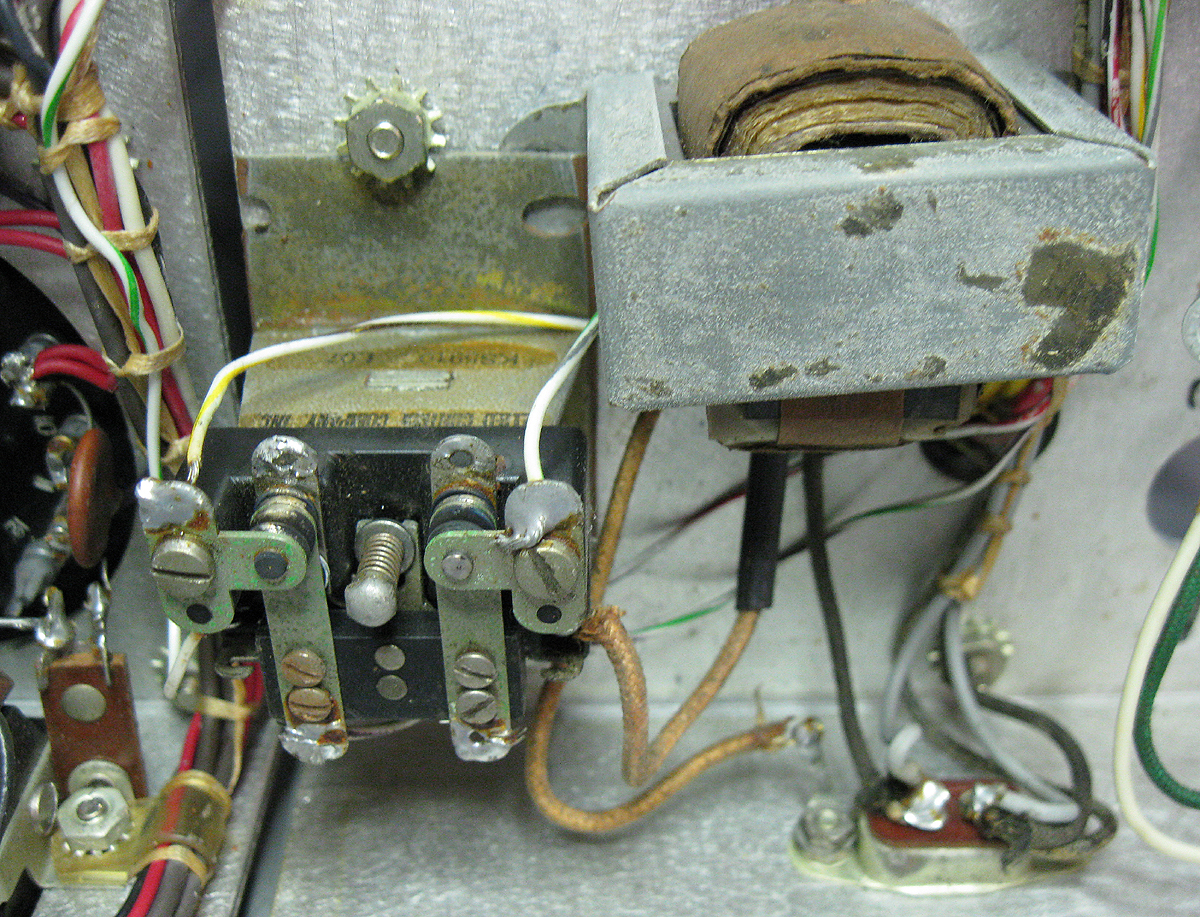
This is an image of the adhoc PTT circuit that existed when I received this radio:
 The redesigned circuit needed to be installed in the same location under the chassis as this previous circuit, but also it had to contain the parts for a full wave DC power supply. I did not want to use any of the DC from the radio itself in an attempt to not take away from the tranmitters CCS rating. I chose a small 12V sealed relay, a 12VCT transformer of an appropriate current rating for the coil, and small terminal strip to mount the rectifiers and filter cap for the power supply.Several functions had to be accomplished in the relay. On PTT, the relay must be energized. This engages the contacts to the plate transformer center tap to be connected to ground and the "Plate On" indicator lamp to be connected to the 6.3V filament voltage of the radio. Energizing the relay is accomplished by the mic switch connecting the PTT relay transformers center tap to ground. This keeps any microphone used at ground potential.Fortunately the simplicity of this transmitters design allowed for an easy addition of true PTT function to be added. This circuit is obviously not complicated. What was more complicated was connecting everything up in a way that addressed the modularity and adding this wiring to the existing harnesses.This is an image of the new PPT circuit installed into the radio in the old location.
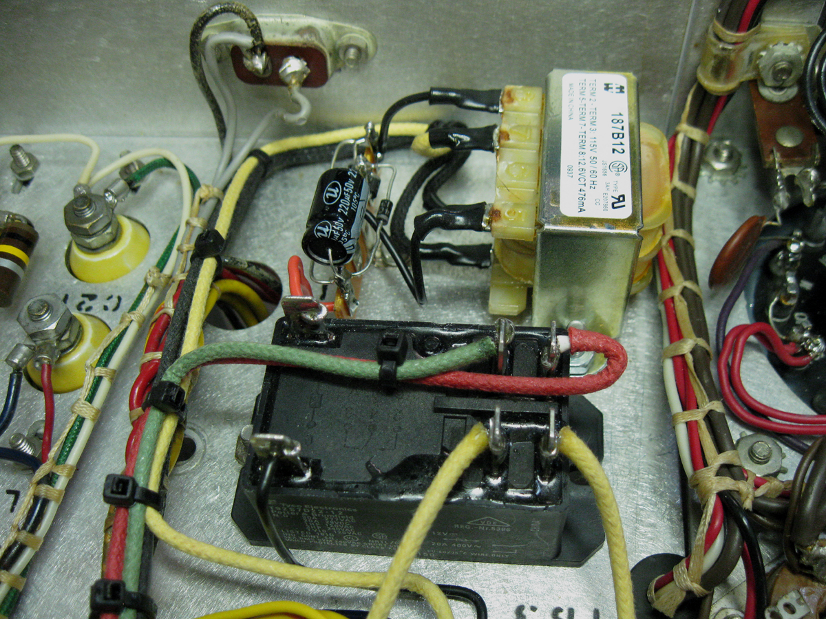 As you can see the entire circuit is located underneath inside the chassis directly below the plate transformer. Only two additional holes were needed to be drilled since existing hardware used for mounting the transformer were utilized. The two new holes are located underneath the transformer and were countersunk to accomodate stainless steel Philips flat head hardware making them flush mount. This way they do not interfere with the transformer mounting. This also allows these additional holes to be unseen in the final assembled radio.
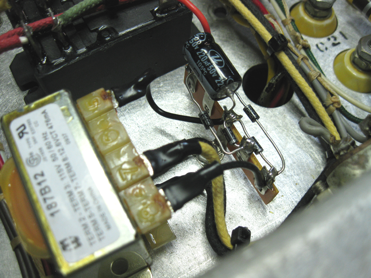 There is a full-wave rectifier and 220uf of filtering on the PSU for this design. It is built up using a standard terminal strip and using 1N4007 diodes and a 220uf 50V electrolytic capacitor. This may be more then what is needed, but I fiqured why not. The parts are inexpensive and small enough. The transformer is Hammond Mfg. 187B12 transformer, 12.6VCT @476mA which is more than enough current needed for this relay coil.
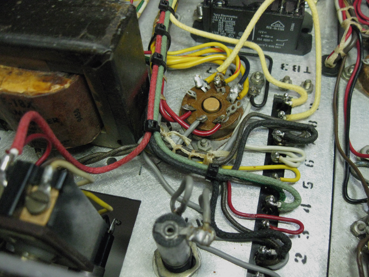 The wiring for the circuit was added and strapped separately and attached to follow the exitsting wiring harness. All connections were made to the solder terminals on the underside of the terminal strip. A single wire was added from the microphone connector added to the wiring harness on the modulator module. It was terminated with spade connector and was run in the modulator harness to the terminal strip. For the PTT line coming from the mic, the unused terminal 9 of the terminal strip was utilized for interconnection between the modulator and the PSU modules.The relay chosen has contacts that exceed the maximum possible current draw (even at low AC line voltage) by three times. The transformer for the relay has a CCS current rating twice that of the draw of the supply and the relay coil. The cloth covered stranded wiring is also overated for current. These design features are inline with the CCS rating nature of this transmitter.
More to come as time permits ...
All text and images contained herein are under strict copyright.
Reprinting or publication in any medium is not allowed without express written consent of the author.
Copyright 2012 John LeVasseur