Gates Radio M-5078 Commercial SW AM/CWTransmitter
Restoration Details - Part Nine
As of this writing it has been quite a few years since I have written anything about this transmitter restoration. I have moved, closed down a business, had some surgery, and other life issues that have kept me away from working on this transmitter. Mostly I have been busy with other ventures, restoring tube gear for recording studios and audio, as well as building custom water-cooled computers for gamers. This has taking up a lot of my time. However, I have started the process of picking this up again, and gathering up my thoughts on what to do next. I should be able to start-up again on this project very soon and will be posting more on this article over the next few months. There is still much to do, even though the radio is now 90% complete. However, a few preliminary thoughts ...
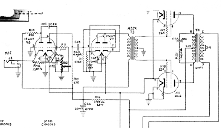
Upon further and recent research on the matter, it appears the previous idea about a user changing the Gates schematic was actually a factory revision. From the factory, the audio section consists of two 12AU7 amplifier tubes and two 6L6 tubes operating as class "B" modulators.
One triode of the first 12AU7 (V8) is operated as a grounded grid amplifier. This type of operation provides a low impedance input in the cathode section circuit of V8. Voltage and current needed to operate a carbon microphone is furnished by the current draw from V8 and the voltage drop across the cathode resistor and the carbon microphone. The second triode section of V8 drives the grid of the second 12AU7 (V9). Then, on V9 both triode sections are connected in parallel and the plates are transformer coupled to the input of the 6L6 modulator tubes.
Below you can see in the schematic I had at the time. You can clearly see the change made on the drawing of the cathode circuit in the first audio stage on V8a, as well as the transmitter's original grounded-grid cathode-input design.
So first, my idea that 12AX7 tubes were used was wrong, and second, I forgot about carbon microphones and their need for voltage. So I have to rethink my approach, and I am torn between trying to keep the radio historically accurate (by maintaining the carbon mic input) or modifying the circuit either in part or in whole. Ether way, I can still add a RFI filtered line input, however now I'm also considering adding a high-quality input transformer that can drive a grid directly, possibly a Jensen. Clearly, I have some thinking to do ...
Gates Radio Corporation has gone through several changes over the decades. Being taken in by Harris Intertype, and now being renamed GatesAir. However the old Gates plant in Qunicy, Illinois is still where technical support is based, along with some of the manufacturing of current GatesAir products. I figured I'd give it a shot and call. After some initial conversations, a man was put on the phone who actually was around at Gates Radio when this transmitter was built. He remembered these transmitters, and talked at length about how they were trying to hit the commercial market and that it didn't go as planned. We talked a little more and said he'd look into what archival info remained and see if he could find anything for this transmitter.
A few days later I got a call back from him. He had found most of the original drawings and schematics, and even an orignal user manual. He had taken all the drawings and had them scanned and reprinted, and took my address info to send them off to me. These are not only the schematic and manual, but also the production drawings and parts lists with vendor information and vendor part ID numbers. So pretty soon, I will have all the documentation I could ever hope for.
In our second conversation, he could see on the documents that only about 78 of these were ever produced, and based on the serial number, mine is number 26 manufactured in last quarter of 1957; apparently early in the production of these transmitters. It was originally sold to a timber company that was operating in upstate New York. He also went on to mention he has never heard or seen anyone actually having one of these or others in its series, and suspects this may be the only surviving example, as far as he knows.
I suspect many of these transmitters were simply abandoned where they were. Considering the remote nature of where they were used this could certainly be the case. Most were used on fixed "company" frequencies and once installed were normally operated by non-professional radio operators or simply by staff. The dial locks and total lack of any controls (like mic gain) are indicative of a design based on specific application. It was designed to be "set and forget". Turn-key, for all intents and purposes. Turn it on ... key the mic and talk. That's it. So many of them were most likely abandoned in-situ.
Companies and expeditionary organizations were not concerned about recouping the cost of such things, and unlike the military, did not sell off relatively inexpensive assets such as these for surplus. They were simple write-offs. Especially the lower-watt class transmitters from this series due to its lower cost when compared to the KW class models. So this transmitter I have may be the only one of this class to survive. After all these years of working on this transmitter I have yet to find any other information or even talk about another one online; other than what I have posted here and on several Amateur Radio forums.
So after having a few days to think on the issue of the audio section. I have decided to go ahead and make the radio practical for operating, however not be as historically accurate. However I think I have come up with some modifications that are both reversible and have minimal impact on the original appearance of the transmitter. I also discovered a few more things that needed correcting from earlier attempts by former owners to repair/modify this transmitter.
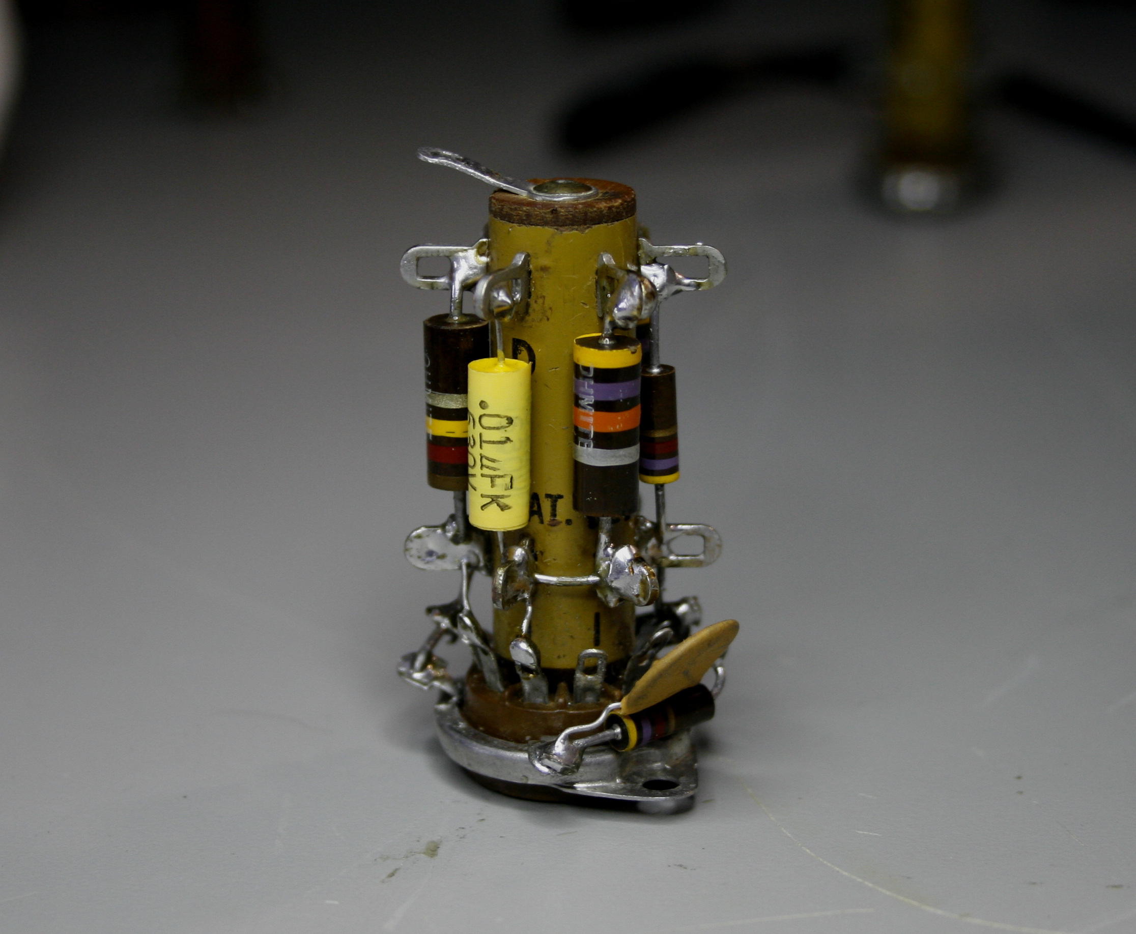
During my initial inspection of the audio section, I had noticed the riser sections on the two Vector 9-pin tube sockets where different heights. Knowing different Vector sockets were made, I just assumed they were different models. However, it still seemed strange to me at the time that Gates would do this in production. So I put it in back of mind and moved on. Upon closer recent inspection I realized one was missing the cap and solder lug on the top (or bottom) of the riser. Instead a nut was holding the cover in place and the solder lug missing completely. You can see this below ...
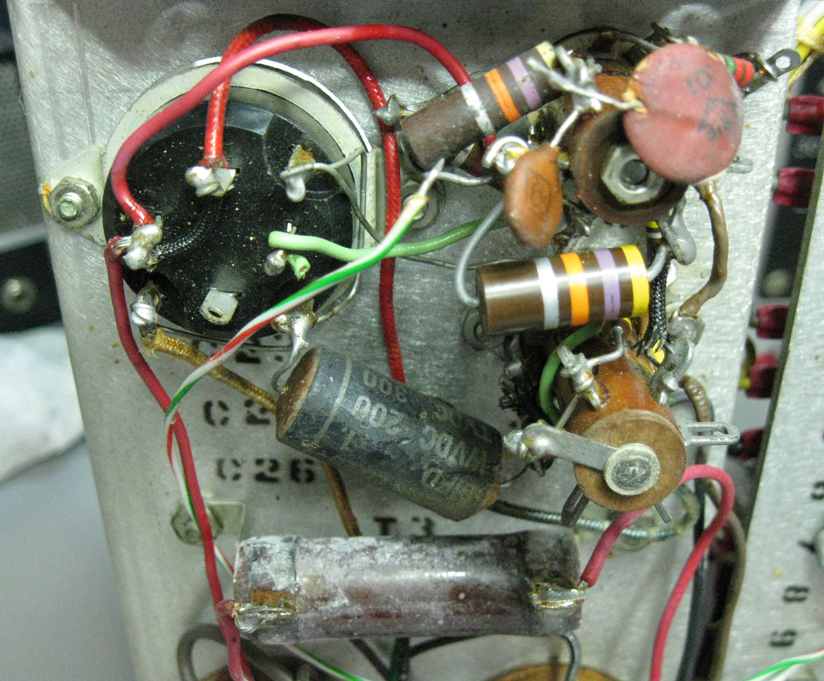
Now that I picked up this project again, I decided to completely replace all of the components in the audio section up to the modulator tubes. I will carefully quality control values and lower the tolerances of all components to 5%. However, once I had stripped away all the various capacitors & resistors from around the Vector socket lugs, I discovered what had been done. On the first 12AU7 (V8) the socket itself was replaced with a white ceramic socket. This is the type with the collar for the tube shield press-fit around the socket. This requires the socket collar to be mounted on the top-side of the chassis. This differs from the Vector socket which is mounted underneath. So, not only was the bobbin with the lugs lower than the other (viewing from the underneath of the chassis), the tube itself is raised about 3/8" above its partner on the top-side. The bobbin from the original socket was put in-place and held in place with a steel threaded rod and nuts. Alarmingly, no insulation on the rod going through the bobbin! You can see the issue in the image below.
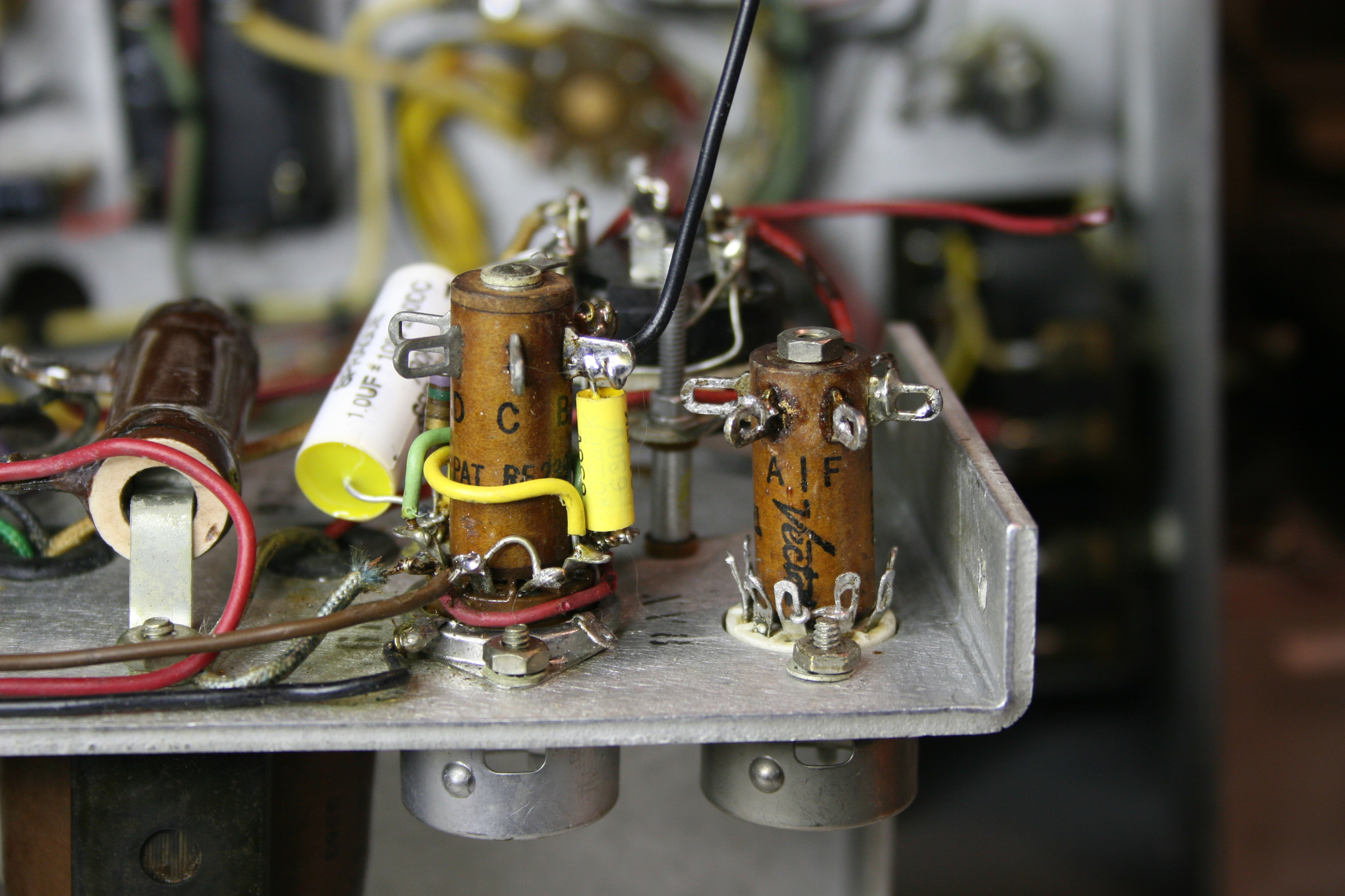
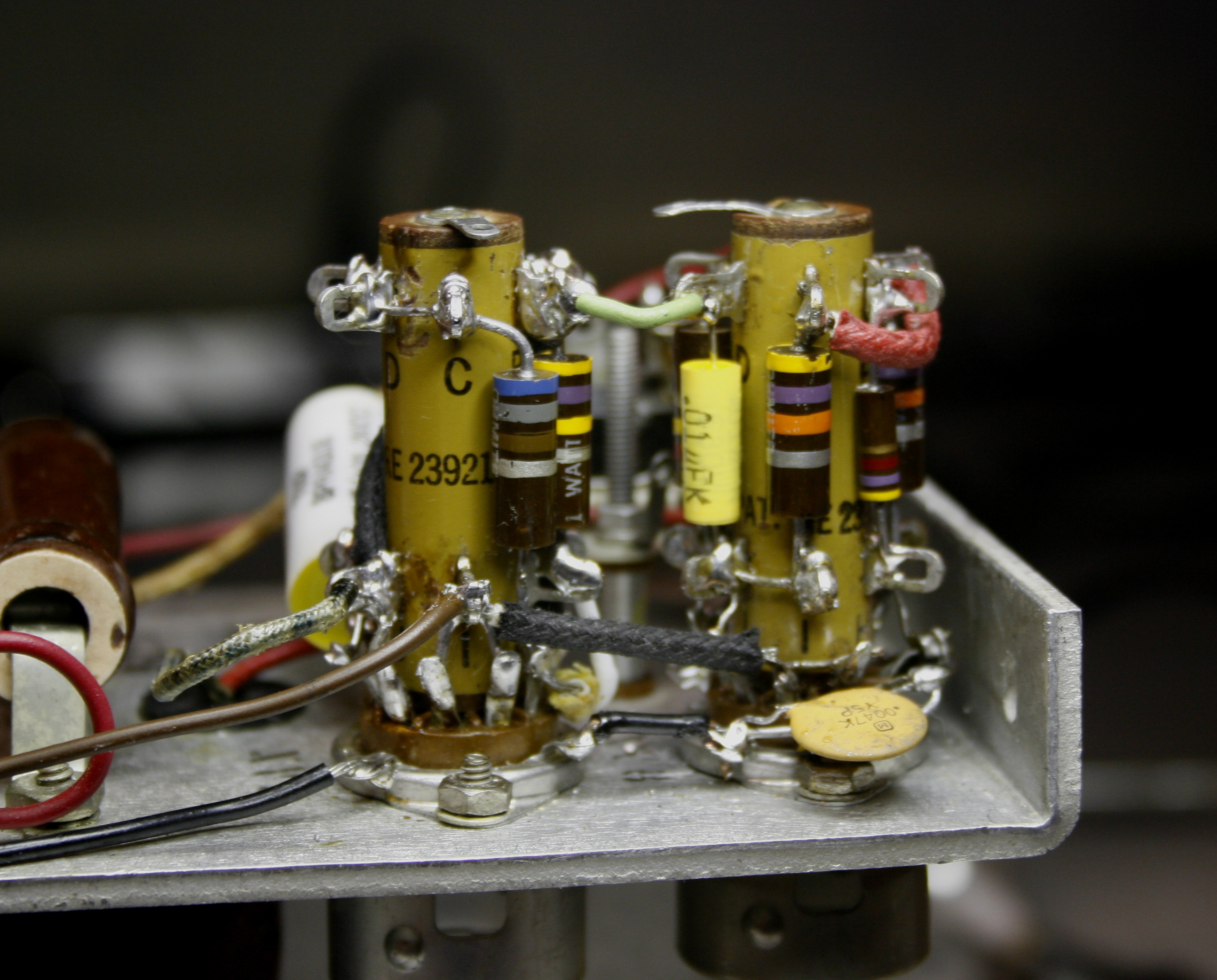
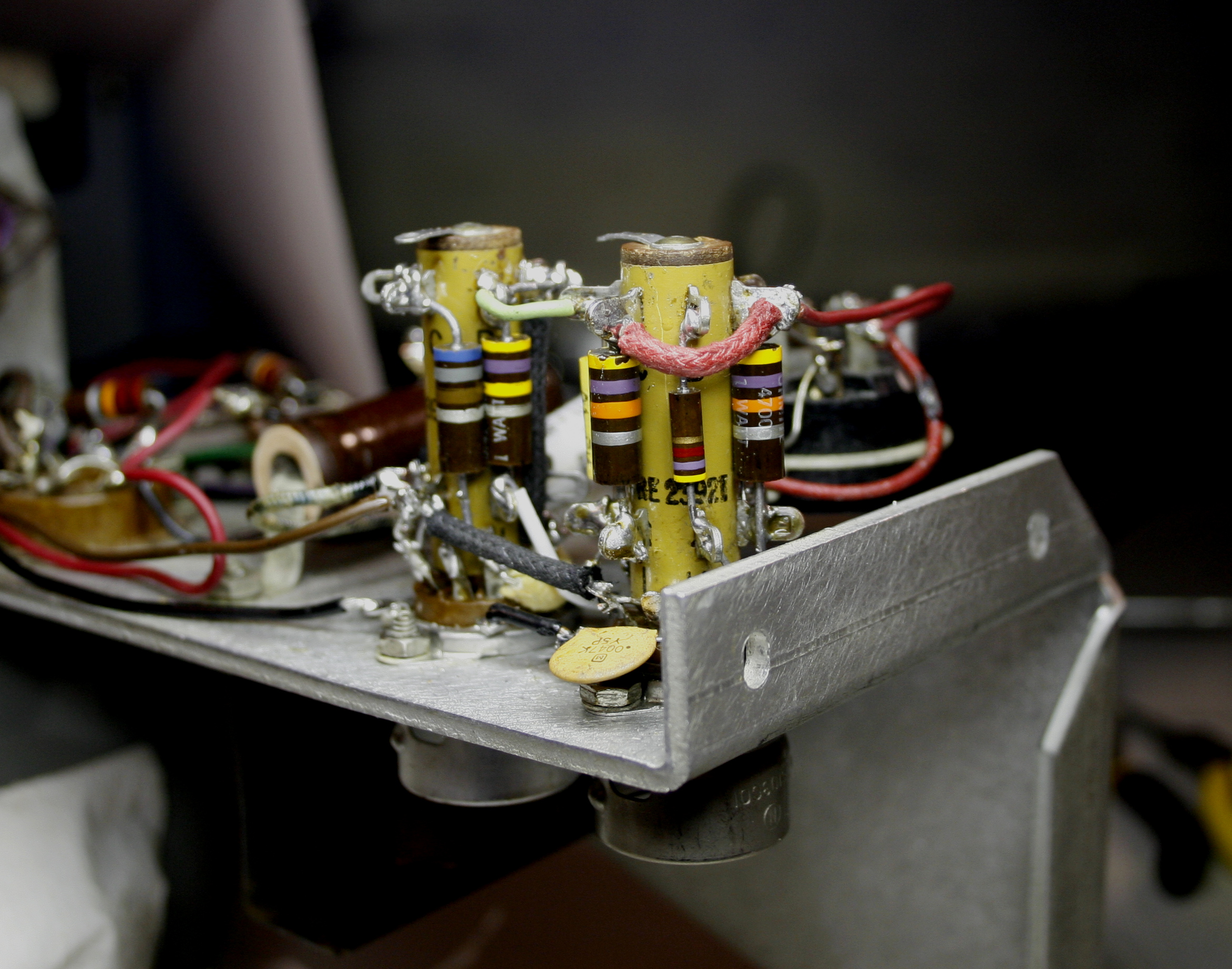
Fortunately, I have a large inventory of NOS parts, such as these Vector sockets, so it was easy to replace with an original part. The thing I always liked about these sockets is the fact that most, if not all, of the circuit for a given tube can be assembled vertically, outside of the chassis. This makes for very short lead lengths, ease of assembly, and a very neat appearance. The socket can then be mounted and interconnecting wires added between tubes. Even interstage coupling caps can be installed between the socket pins and the bobbin lugs, so the only thing needed to be added once the socket is mounted are interconnecting wires. Even grounded components like bypass caps can be assembled off-chassis since four ground lugs exists around the base on the socket collar. Love these things! All of this was something totally lost on whomever last serviced this transmitter, looking at the rats nest of leads and components in the first image above.
So with my NOS Vector socket in hand, I went about building up the audio section I had designed. The specific circuit design is detailed further down on this page. The first image shows the new sockets before assembly. You can see in the next few images the first and second mic stages fully assembled before installing onto the chassis. Most of the components are mounted vertically, close to the bobbin. This assures the shortest possible lead lengths, which in a high-gain audio circuit stability is assured. Stray capacitance and parasitics are kept to a minimum. In the images below you can see the first two audio stages on V8 are all contained on the socket bobbin, including the B+ load resistors and decoupling capacitors and resistors for each triode section. The only things leading to or away from the socket are interconnections between V8 & V9, as well as filament & B+ leads; along with the leads to the cathode electrolytic caps. The cathode caps are in the multi-cap twistlock, located behing the sockets. None of the components are hanging between tubes. The only exception is the white and yellow cathode bypass cap on V9, which is physically too large for the bobbins. The other images show the sockets installed in their final positions with all leads attached. Neat!
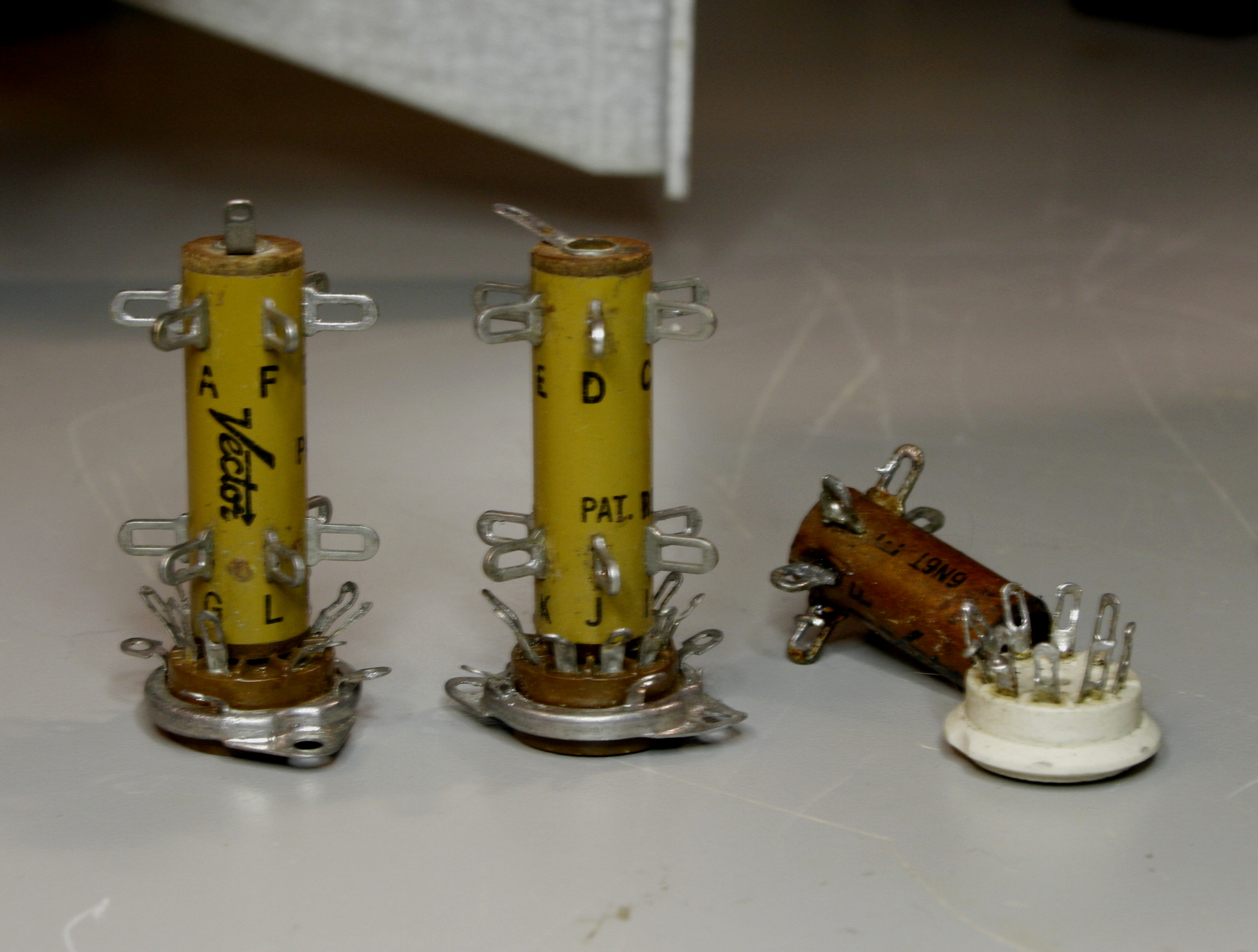
Vector sockets use Micalex. Many people remove "brown" sockets from their radios thinking falsely that they arc over due to deterioration over time. However, once again this is myth mostly because people do not understand the difference in materials and project the poor characteristics of one material on a completely different one. Phenolics (sometimes referred to as Bakelite) do arc over, especially at high-frequencies or voltages. They also are very poor at resisting humidity. The arcing issue happens on some older radios in the case of high-voltage rectifier tubes of high-power amplfiers that use phenolic sockets. Phenolic does break down from heat and humidity. Unglazed ceramic sockets can also be prone to this problem. Micalex was the answer to this problem. And while Micalex looks like phenolic (being brown) people think they are the same thing. Far from it. In fact Micalex is far superior to even unglazed ceramic in this application in all but the highest frequency, temperature, or voltage extremes. Micalex is an insulating material made by heating and compression-molding the mixture of natural or synthetic mica with glass powder. So while technically it is a ceramic, it is one that exhibits excellent resistance to water, oil and weather, is machinable and exhibits excellent electrical properties, especially at high frequencies.
While I would love to show you a schematic, I don't have to drawing software to do it right now. So instead I'll decribe the changes I have made textually. The circuit differs mainly in the microphone pre-amplifier first & second stages and slight changes to the driver stage. No change was made to the modulator, with the exception of removing one capacitor which was across the input of the modulation transformer primary.
● First Audio Amplifier
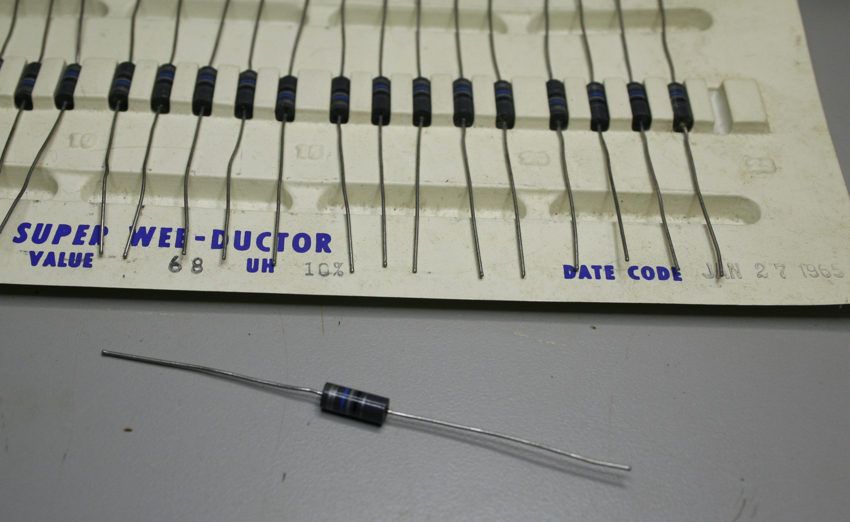
The most significant change was made in converting the microphone first stage from grounded-grid cathode driven input to a more standard grid input type. At the input on the microphone connector the signal first goes through a second order filter composed of a 68µH inductor in series, with a 47pF bypass capacitor following it.This should present a high-impedance to any signals above ~500kHz, therefore reducing possible RFI at the grid input. The inductor is a small low-resistance (2Ω) molded type, about the size of a 1/4 W carbon resistor.
The first audio amplifier (V8a) does not have an input coupling capacitor. If a dynamic microphone is connected to the mic jack, the low DC resistance of the microphone will short-circuit the grid bias on the tube to ground, removing the grid bias of the tube, and upsetting the operation of the circuit. A 47k isolation resistor limits the amount of current that can be drawn by a dynamic microphone, so that the bias on the tube will not be completely short circuited. It is also true that this resistor and a 1M grid resistor function as a voltage divider for the input audio, but the small value of the isolation resistor compared to the grid resistor means that the audio is reduced by only 0.5%, an insignificant amount. The grid resistor provides a load for the microphone and allows the DC bias developed by the cathode bias resistor to pass through to the grid of the tube.
Without cathode bypass capacitors, the voltage developed by the cathode bias resistor would fluctuate with the varying plate current and produce negative feedback, lowering the gain of the stage. The cathode bypass capacitors smooth out the variations and provide a steady bias for the triode. The plate/cathode current contains both a DC component and an AC component (the output signal). The bypass capacitors shunt the AC component around the cathode bias resistor so that only the DC component contributes to the cathode bias. Furthermore, to make sure that any stray RF in the transmitter doesn't effect the bias, two capacitors are used in parallel. The first is the main 20µF audio bypass capacitor. However, electrolytic capacitors such as this can have high stray inductance and not function well at radio frequencies. To insure that the 4.7k cathode bias resistor is also bypassed for RF, a .005 ceramic capacitor is placed in parallel with electrolytic. Whatever isn't bypassed by one is then bypassed by the other.
In the original circuit, a 500pF interstage coupling capacitor couples the audio output of the first audio amplifier (V8a) to the input of the second audio amplifier (V8b), while preventing the plate voltage on the first audio amplifier from getting through. The reactance of this capacitor is quite high at the lower audio frequencies. For example, the reactance is about 1Mohm at 100Hz. This was done intentionally to lower the response at the lower audio frequencies. Keeping the response down at the lower audio frequencies in theory leaves more room for the mid and high frequencies, and improves the overall communications effectiveness of the final transmitter signal. However, I decided better audio fidelity is preferred over communications effectiveness. To increase the bass response, this capacitor was increased in value to 0.02µf.
The varying current drawn by the tube can cause a slight variation in the low B+ supply voltage, which can have an undesirable affect on other stages operating from the low B+ supply. A .1µf decoupling capacitor and a 220k decoupling resistor smooth out these variations, preventing them from affecting the low B+ supply voltage and affecting other stages.
● Second Audio Amplifier
The second audio stage has fewer changes, however many are similar. One of the more significant ones being the addition of 100k potentiometer to control the gain of the stage, in place of the fixed grid resistor. Along with that the same changes were made to the cathode circuit, the B+ decoupling, and interstage coupling; made with the same values as the first stage.
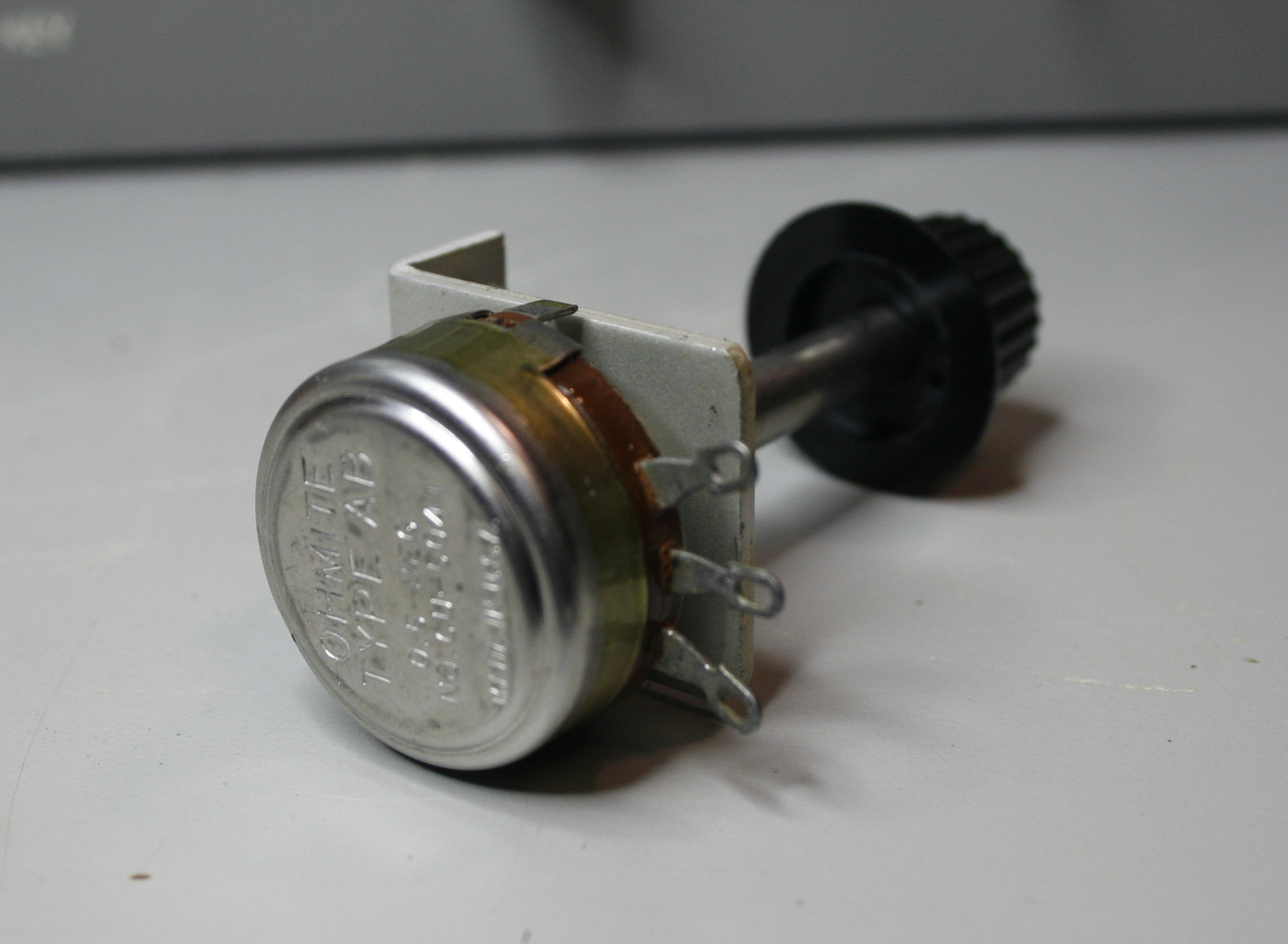
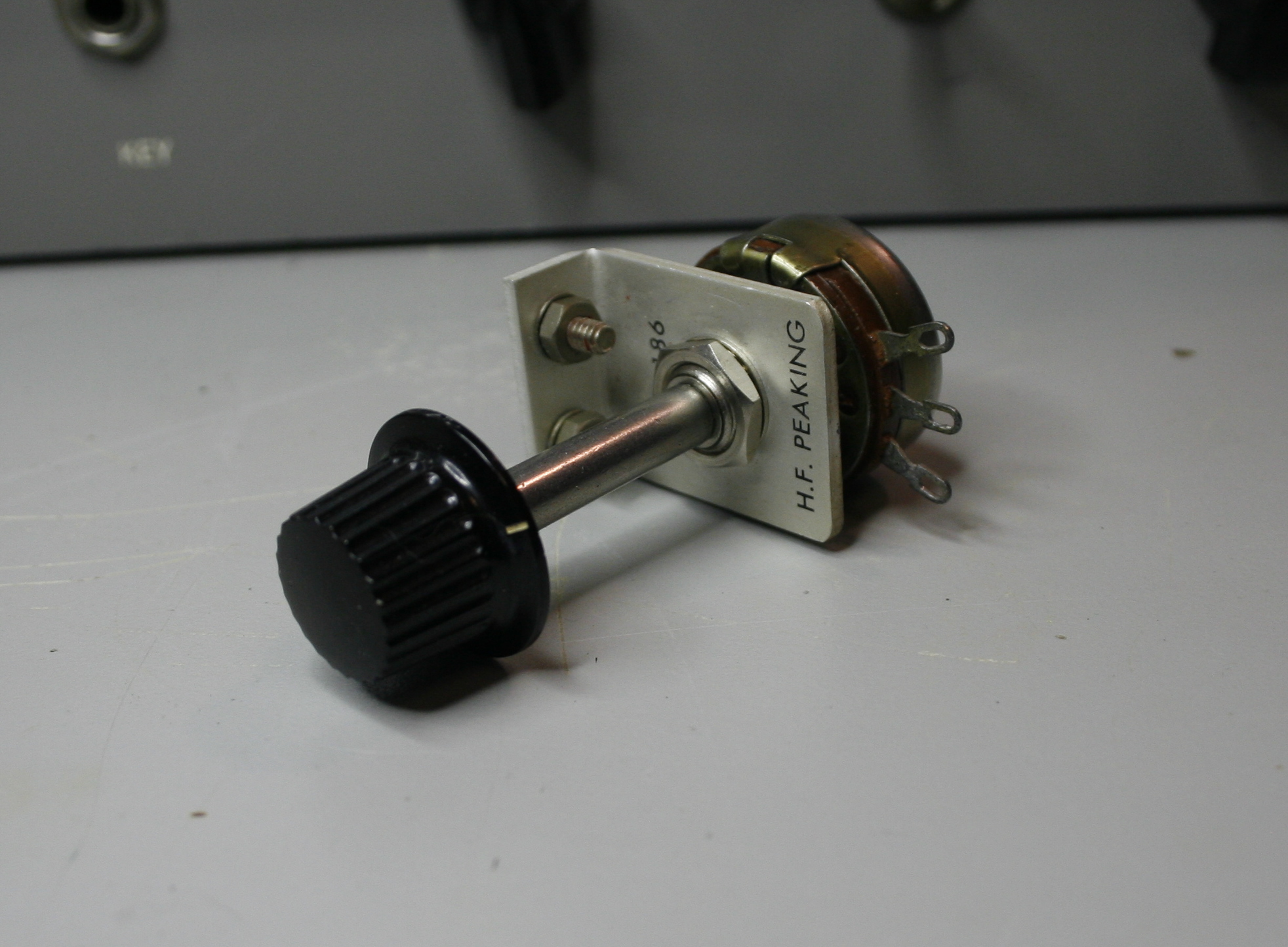
The new audio gain control functions as a voltage divider on the incoming signal. For this I used a NOS Ohmmite Type AB potentiometer 100k/2W mounted on a L-bracket I had. A fraction of the signal passing through the input coupling capacitor is applied to the grid of the second audio triode (V8b) via the wiper of the pot, depending on the setting of the new "Audio" control. The audio gain control also functions as a grid resistor by allowing the DC bias developed by the cathode bias resistor to pass through to the grid of the tube. The 2W rating of this resistor is more than sufficient for this purpose. Here's some images of the pot and bracket before installation.
● Driver Amplifier
The driver stage, which feeds the primary of an interstage transformer (Triad A-33x) as a single-ended amplifier and uses both triodes of the 12AU7 (V9) in parallel. This provide sufficient gain to drive the grids of the modulator tubes. It operates more as a current amplifier and not as a voltage amplifier.
The only change I made here was the addition of a .005pf filament bypass capacitor. This capacitor is connected between the hot filament lead and ground to eliminate any stray RF that may have gotten onto the filament supply line. The capacitor prevents the RF from getting into the tube filament and into the audio chain through the cathode to filament capacitance of the audio driver tube.
I am still thinking about how to attempt to provide some negative feedback to the input of this stage from the output of the modulation transformer, and do so in a way that does not effect that output. Additionally, I do not want to reduce the gain of the driver to a degree where modulation becomes limited. So I'm still pondering that option, which can be added at anytime in the future, if needed.
● Line Input Modification
Previously in this article I briefly touched upon adding a line input to the transmitter, which is still the plan. I am still working on that part of the circuit design; especially considering I have decided to add an audio gain control. The line input, which will have its gain determined by whatever outboard audio gear I employ, will also need to be isolated. In other words that input cannot be effected by the first audio stage. So a switch is necessary that both engages the line input and retain a load for the switched-out first stage plate, which will then be idle.
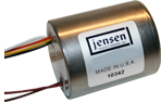
I think I have worked out the best approach on the line input circuit; one that offers both the best fidelity and has low impact on any the physical changes to the transmitter. First I do intend to incorporate a Jensen JT-11P4-1 line to grid audio transformer. I am very familiar with these since I have a few and used them extensively while working the pro-audio field. These are designed specifically for this application; line input into the gird of a 12AX7/12AU7 grid. The -3dB frequency response is .2Hz-80kHz and flat from 20-20k. This broadbanded design means that in the audio passband the phase response is almost perfect; with little or no variations in phase response over the entire 20-20kHz range. Additionally, distortion remains very low and CMRR remains high, even when driven by high source impedance. The primary is fully balanced and its leads may be reversed to invert polarity, if required. A 30 dB magnetic shield package is standard.
The transformer is tiny. It is contained in a "can", with two mounting holes underneath, and has wire leads. The JT-11P4-1 measure 1" tall, 1" in diameter. It will be easy to mount this on an angle bracket on the under-side of the chassis, directly below the interstage driver transformer. A single small shielded wire (grounded only at the switch side) will be fed from the secondary of the Jensen to the top-side via a hole for the interstage transformer wiring. All other wiring of the Jensen will remain on the under-side of the chassis. Here's a picture of a similar type of transformer for reference.
The circuit will employ an XLR type connector added to the rear. Pins 1 & 2 will employ the same 68µh inductor and bypass cap as the mic input; which go to the primary of the Jensen transformer via a small balanced shielded cable (how the shield is grounded will be determined during installation and testing). The positive side of the secondary of the winding is then brought to a 20k resistor on one side of a SPDT micro-switch which will be located next to the mic gain control pot. This 20k resistor will be acting as a grid resistor for V8b when in the "line" position. The other grid resistor (the gain pot) normally used by the first audio stage will have its wiper, connected to the other side of the switch, disengaged from the grid of V8b, but the rest will remain grounded to provide a load for the plate of the first stage (V8a). The common of the switch is wired to the grid of V8b.
Having separate switchable grid resistors insures proper matching and loading on the grid and source, given one is sourced from the plate of a triode and the other a transformer which have inherently different impedance. This line input circuit is simple; yet will offer high-fidelity, low susceptibility to RFI, and be nearly invisible. I promise to take photos and post this modification in a future installment, when I actually perform this work.
● Final Thoughts and Musings
Nothing in this design is ground breaking. I went with a design that is fairly ordinary. One reason was to attempt to apply a design that is accepted as good engineering practice and is known to be stable & reliable. Another reason was in attempting to use a design that is typical within the time period this transmitter was manufactured, that being the late 1950's early 1960's. In fact, this circuit is very similar to one used in transmitters such as the Johnson Viking Ranger, less all the bandwidth limitations built into that design. The goal simply was to redesign the audio section to be similar to the original, use the same tube compliment, allow the use of modern microphones and outboard audio processing and yet have higher fidelity.
I am excited to see how this looks and sounds once I get the transmitter completed and have the time to do thorough testing of its performance parameters. I will post all the images and final test results in a future part of this article.
My only two points of concern at this point are the driver transformer and the class B modulator. The Triad A-33x is an OK interstage transformer, however its specified frequency response is limited to 70-7khz. This should be fine, however I would prefer the A-35x, which would look the same, bolt right in, yet offer a little broader response at 50-10kHz. However, any interstage transformers at this point (which I have very few of) are priced out to ridiculous amounts, even the A-35x due to the audiofool and DIY markets being what they are. I would prefer a good UTC LS series interstage, however the correct one for this circuit are currently selling for over $500USD in good condition; which is crazy stupid expensive. And the only interstage transformers being made now are simple 1:1 coupling designs, where this circuit needs impedance matching at a 1:3 ratio. Damn the audiofools!
As far as the modulator class is concerned, I am now considering changing it over to class Ab, however I will have to see whether or not the negative voltage already in the radio used for the keying circuit is sufficient as a bias voltage supply for the 6L6 modulator tubes. Regulation is of key concern, so I will have wait and see once the radio is fully assembled and do some stress testing on the negative supply.
Junkbox vs. NOS (New Old Stock)
Many people have their "junkbox" which they use to have parts available for restoration or refurbishing boatanchors. I have always had an issue with anything called "junk". While sure, many old used parts are perfectly acceptable; however their long-term reliability is always dubious at best. So I have over the years concentrated on only acquiring NOS (New Old Stock) on vintage components. If I am going to spend money on parts, it doesn't make sense to do so on old parts where their provenance is questionable. Electrolytic and paper/oil caps are never usable by me in my opinion, even if unused or "new". Modern alternatives are available cheap on these type of components.
I search out NOS parts at Hamfests, go to estate sales, and recently found a cache of NOS parts when Dowling University on Long Island recently closed down. My cousin worked as faculty there (Biology dept) and she told me about an "old radio" used by the Physics professor that I could come and have. Turns out it was a National RBL-5 "Lowfer" receiver in near pristine condition with the original manual. (I plan to do another article on this radio while I restore it). When she took me to small backroom where the receiver was being stored, I noticed Ohmite boxes (actually cases) stacked up and many other racks with drawers nearby.
Upon inspection they contained boxes and boxes of Ohmite "Little Devil" carbon composition resistors, many sleeves of Allen-Bradley carbon composition resistors, boxes of various Centralabs rotary switches, and hundreds of Type J and Type AB Ohmite sealed pots, just to name a few of the parts found. There were also several boxes full of useful NOS tubes, mostly receiving and small amplifier tubes, all RCA from the 60's. There were dozens of 12AX7 and similar. All parts were low tolerance (5% or better), and all mil-spec. All where new unused. When I asked she said I could take it all if I wanted, since they were all going to be thrown out anyway. So I went back to the van, which I fortunately had a bunch of boxes (just in case) and filled the van with NOS parts. Yes ... it did fill the van. I was dumbfounded by my luck on finding this cache. The receiver was cool, but this cache of NOS passive parts was a windfall beyond measure. Here's and image of some of the parts boxes, which I am still sorting out and organizing.

Those Ohmite boxes are 50 count. Besides all of the tubes, the thought that I would have every value in everything from 1/8W to 2W in these quantities NOS on Ohmite carbon comps, not to mention nearly as many sleeves of Allen Bradley types, along with Type J and Type AB variables, never entered my mind as even a remote possibility. But due to some luck and a constant pursuit of such things, there it is.
Regardless of my luck, understand this is not bragging. I took the time to look and search these out. I cannot stress more strongly, if you are serious of doing high-quality restorations of boatanchors, the need to take the time and search out only NOS parts. When you accept this mindset you do end up over time with a nice assortment of parts that are reliable; and you can carefully QC values, since you have an assortment. And when you do fix something it works properly and will outlast you in the long run. Having this picky mindset also tends to allow you to come across caches of parts, sometimes as was the case with Dowling closing, large caches. Sometimes even at no cost, something all Hams can appreciate.
For parts that have a shelf life, like electrolytic capacitors and such, there are sources for newly made parts, even having the older values. Such as pre-wwII cap values (40µf vs. 47µf for instance). A great source for these are a place online called JustRadios.com (http://www.justradios.com). Here they have a wide assortment of newly manufactured high-quality NOS passive parts at reasonable prices. They ship fast and have always been fast. They tend to stock higher quality, such as only high temp coefficient caps (105° vs. 85° for instance). They also have good articles, with accurate information, on the differences between the components, the advantages and disadvantages of different types in various applications, etc. I highly recommend this source.
Once you have made the effort you will be able to make perfect repairs and restorations work. It took me only a few years to acquire as much I will ever need in my lifetime. Even though it seems difficult, in reality it wasn't difficult at all. And it's because I refused to settle on having a "junkbox" ever again. After all, it is just junk.
More to Come Soon ...
I promise more to be coming over the next few weeks, so check back from time to time. Thanks for looking and 73 till next time. But before I go, since I have finished the restoration of the RF Deck Chassis & Cabinet here is a moment of zen ...
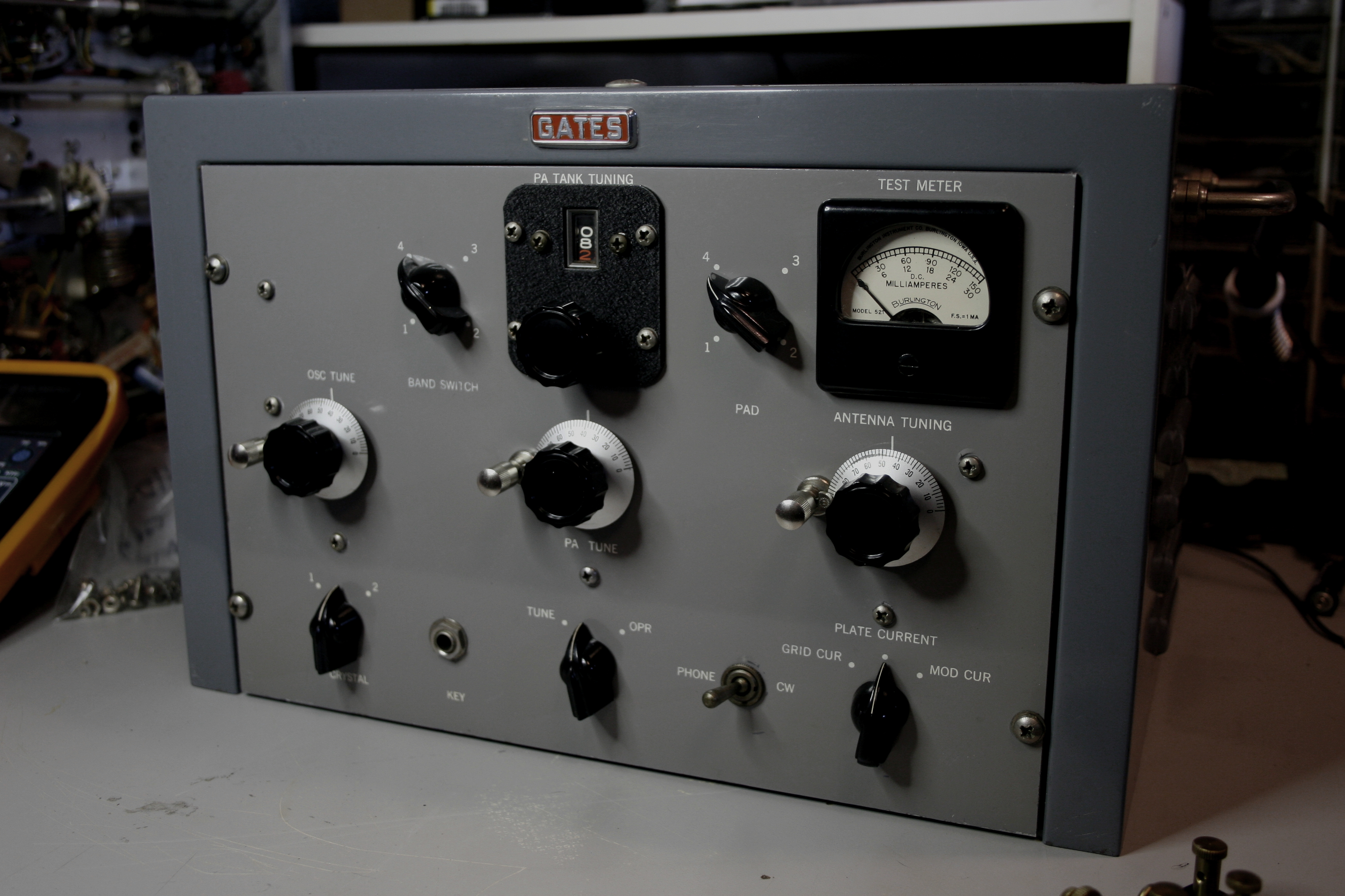

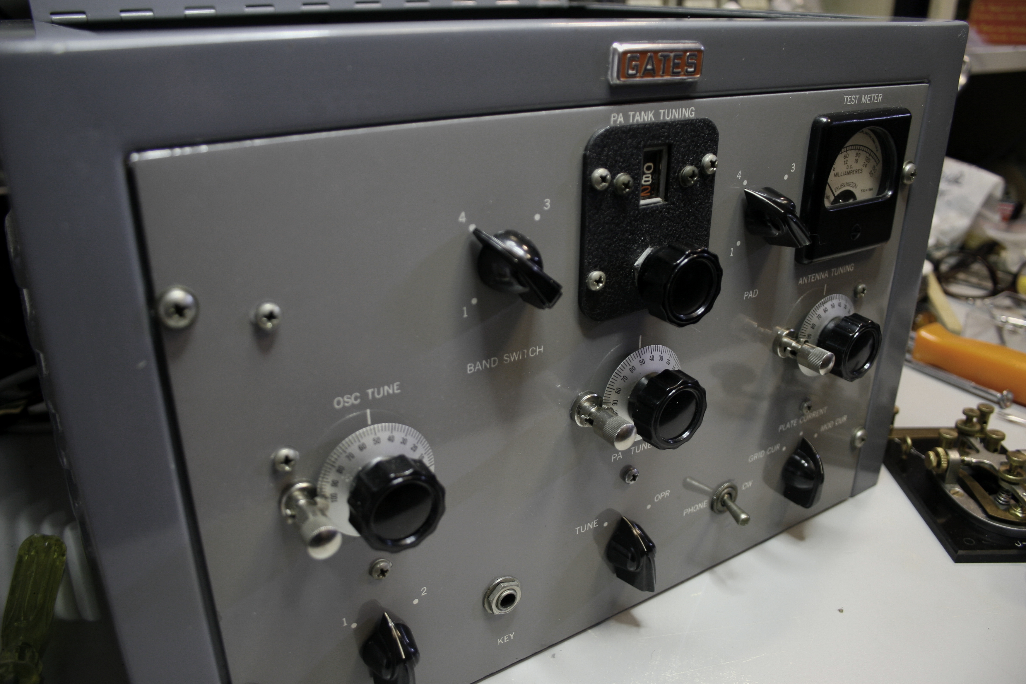
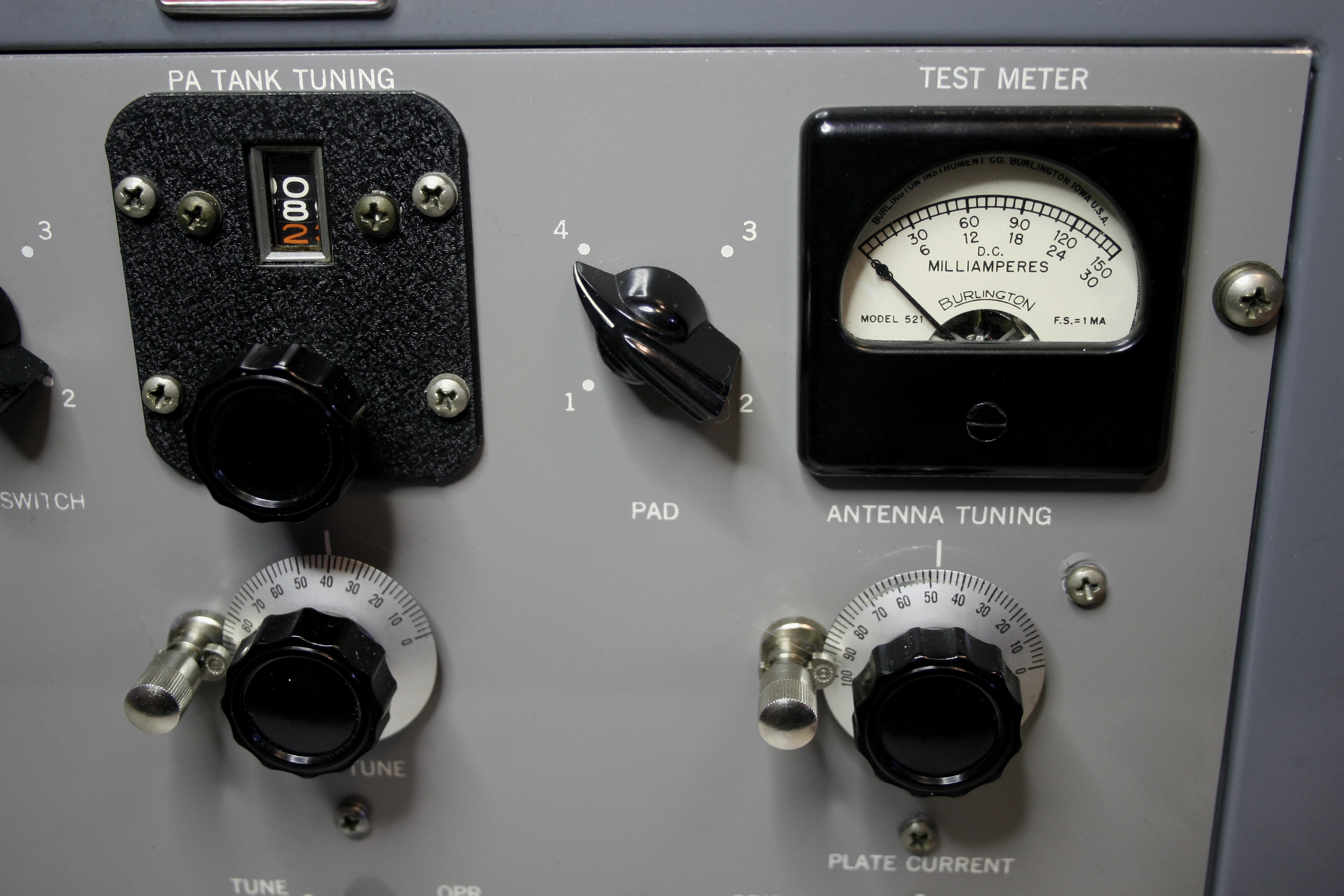
Yeah ... I know, I know. I also just noticed in the images I have to get in there with a soft brush and get the remnants of compounding out of the Gates logo and the screws on top. See ya!
All text and images contained herein are under strict copyright.
Reprinting or publication in any medium is not allowed without express written consent of the author.
Copyright ©2017 John LeVasseur