Gates Radio M-5078 Commercial SW AM/CW Transmitter
Restoration Details - Part Seven
Electronics Evaluation, Testing & Restoration.
Dated: July 1, 2012
I have now completed all of the cosmetic restoration. The chassis has been cleaned and chemically stabilized, rust & corrosion has been removed. The transformers and other components have been repainted and decals have been made and applied. The cabinets & front panels have been cleaned and buffed out. All mechanical components have been properly cleaned and lubricated.
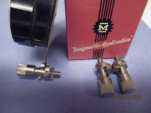
One side note. I was recently able to acquire brand new Millen dial locks for the tuning knobs. These hard to come by items were graciously provided by Richard Cohen, K4ITU. This addition really made the front panel pop with that fresh from the factory look.
Now it is time to begin the task of evaluating, testing and restoring the electronics of this transmitter.
The Importance of Good Documentation
In restoring any radio, it is good practice to acquire as much documentation as possible. This includes schematics, manuals and any information you can find about modifications, known issues, manufacturer upgrades and addendum's. However in many cases this information may be limited at best, as is the case with this transmitter. Online I think more has been said about this radio in this article, than exists anywhere. A manual is available online from one source, and it is incomplete. Harris/Gates has no information available, either online or by phone (which is unusual for them). The schematic I have received is incomplete.
One of the problems encountered when restoring an unfamiliar radio is maintaining the original circuits or even knowing what is original or what is a modification added at some time. And even after getting a schematic this may not help. Case in point. After receiving this manual and schematic, the first audio stage in the schematic shows a change, which is hand drawn in and appears to not be a Gates revision. The original information was erased and drawn over, possibly! It's difficult to tell. As it turns out, this part of the circuit was also modified in the radio itself, and not as shown in this schematic. In fact a completely different tube was used; a 12AX7A instead of the 12AU7. Additionally what is in radio now is a grid driven scheme, where the original Gates design was cathode driven. So at this time it is difficult to know for sure what the original circuit from Gates was.
The following image is the schematic fragments I have. This is four images combined by me into one. The oscillator and final PA circuits have been merged from two images. The supply and audio section are still separated as they were in the original images. As you can see they are as a whole incomplete.
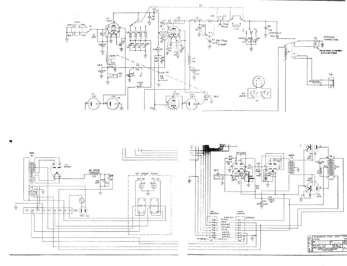 |
So, as you can see without proper documentation it can be difficult to fully restore to original condition a particular circuit. So the best you can do is either interpret what documentation you have, or work out circuit that works for you. In this case, the original circuit was designed for a Carbon mic. I do not intend to use a carbon mic regularly. However, I did find a NOS Astatic 10M5A carbon mic, which is what was originally supplied with this radio from Gates.
 |
I made the decision to try and restore the radio to its original circuit design for the Carbon mic, but also allow the use of an external line in. This will accommodate the audio processing and microphone compliment I am currently using in my station. This will involve bring the tube back to a 12AU7 and rewiring the socket. Also adding a connection to grid input of the second stage wired in from a phone jack to be added at the rear of the modulator deck, with an LC circuit of a series RF choke and bypass cap to help filter any RF coming in on the line level signal. Below is a schematic of this new first and second audio stages.
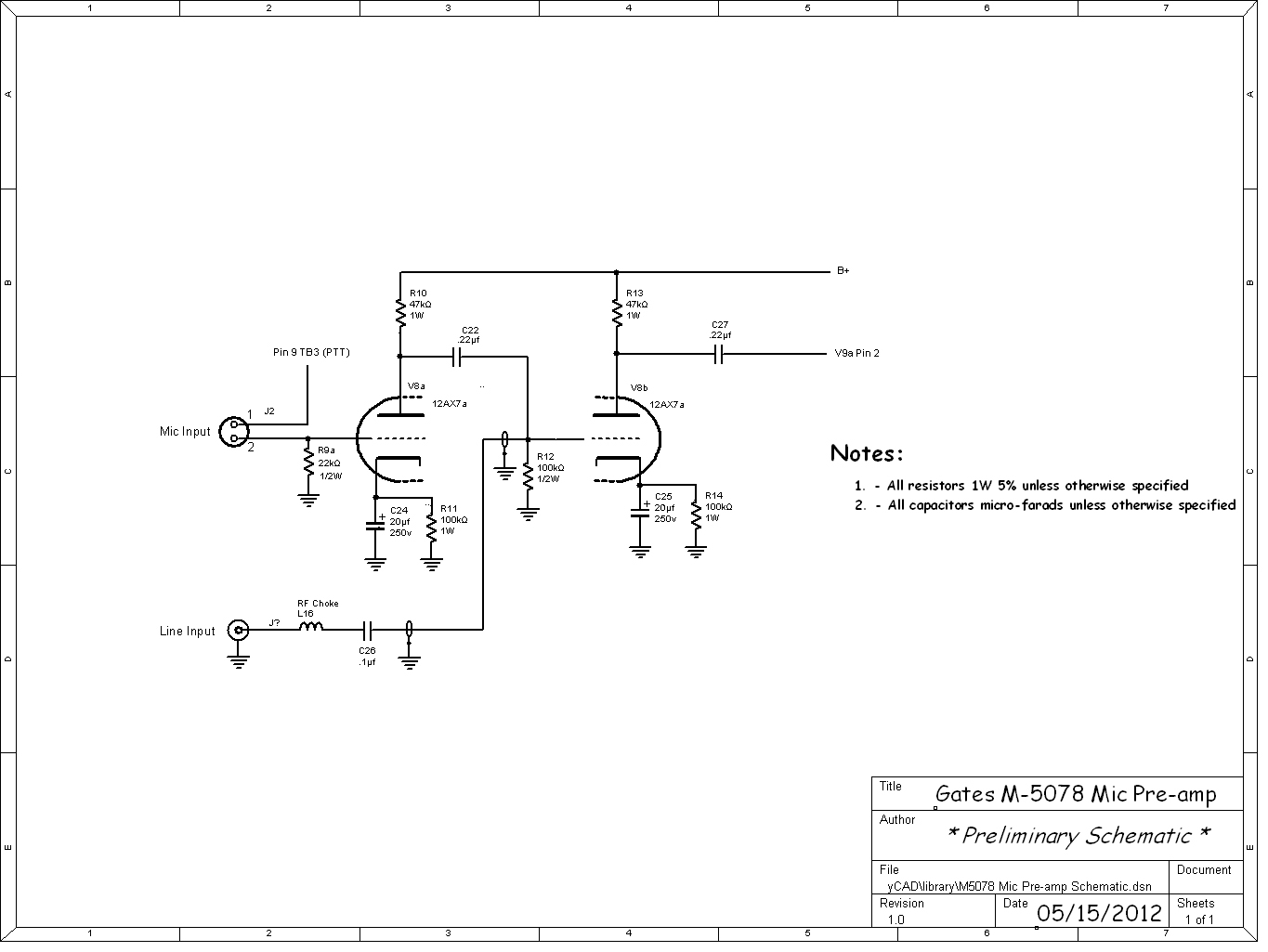
This should satisfy maintaining original specification as well giving some practical usage of my audio chain in the station.
Testing at the Component Level This is probably one of the single most important things you can learn if you decide to begin restoring vintage gear. There are countless "how to" pages on the web on the best procedures for testing and troubleshooting at the component level. Are a few links to pages that go over the basics:
There are of course many books and magazines on the topic. Check you local library. (For you youngsters: A library is a place where they keep books, which are sort of like web pages and blogs but printed on paper and bound. Books work without batteries or power. Imagine that!)
What I will touch on here are some the most common things to look for in any radio of this vintage, while discussing specifics of what I did in this transmitter.
Resistors and Capacitors There are many factors that effect the performance and reliability of old tube electronics. The most common sources of trouble are resistors and capacitors. Both of these components degrade or change value over time. Heat is the primary culprit in degrading these components, while with capacitors moisture and lack of use can cause problems.
Resistors
The most common resistors used in radio of this vintage are carbon composition and wire wound power resistors. Carbon composition resistors are perfect for RF circuits due to their inherently low self inductance. So if the circuit is known to be handling RF it is somewhat important to use only carbon composition resistors. Other more modern types can be problematic in this regard. The inductance value varies greatly by resistor type and even by manufacturer.
One example I can use where this was a problem was where a friend of mine restored a receiver. He replaced all of the resistors in the radio with modern equivalent "carbon film", without understanding the difference between types in regards to inductance. While he was able to recover lost gain, the radio was plagued with numerous "birdies". When I looked at the radio for him, I discovered some of the resistors he installed were actually in self oscillation at various frequencies in certain circuits. This was the source of this birdie problem. I showed him by breaking one these open that the carbon film was actually carbon impregnated onto a fine plastic strip which was helical wound around a ceramic core. Basically forming a small helical coil of carbon. Using a grid dip meter I showed him the various resonances at RF these resistors had. He also was having problems aligning the radio, also cause by this additional inductance in critical frequency circuits. Now, in circuits not handling RF, like in power supply or audio circuits this becomes less critical.
However, carbon resistors have a nasty tendency to change value over time, even those with precision tolerances. Most times the value of resistance climbs to some higher value. Sometimes if they fail completely they show as open. Also many manufacturers would save cost by using wattage ratings close to maximum with no room or reserve left over. This would cause many resistors to operate continuously near their maximum heat tolerances, causing early failure or value change.
Since the Gates here was designed to operate at a CCS rating, most of the resistors in this radio were over-rated in terms of their wattage. Most operate at about 50% of their ratings, with a few exceptions. However, I decided to replace all the resistors with new carbon composition at a higher tolerance and also QC tested for value. So if the original was a 1k 10% I replaced it with a resistor measured at exactly 1k with a 5% tolerance rating or better. In some cases I also increased the wattage rating to the next highest value. All carbon comps used here are mil-spec Ohmite or Allen-Bradley (RC07, RC20, RC45, etc.).
To test a resistor you can simply remove one legs and measure the value on a meter. Or you can just go through like I did and replace them all, which may not be necessary. I did this with the idea of fully restoring this transmitter.
Capacitors
Capacitors present a different set of problems, depending on type and usage. There usually six types of Capacitors used in radios. Mica, Oil, Ceramic, Electrolytic, and PIO (Paper-In-Oil). Basically I listed them in order of reliability, best to worse. Mica and oil caps usually are fairly reliable. This is not to say you should not check them. Ceramic disc capacitors should also be checked but are usually reliable, but less so. Electrolytic and paper types should always be replaced. Most of us understand the issues with electrolytic.
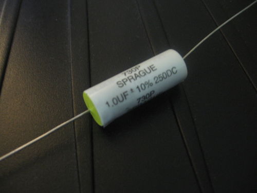
Paper caps, some times referred to as Black Beauties, Mustards or Bumble Bees are almost always bad, even if unused NOS. The are susceptible to moisture and are almost always leaky. While they may test with the correct capacitance most will have very bad leakage. Good axial lead polyproplene caps are good replacements for these. I do not like Orange Drop® types since they are large for their value, expensive and difficult to mount in some circumstances. Most times I use Vishay Sprague 730P types. These are good quality, reliable and inexpensive. They also tend to be the same size or slightly smaller then the PIO types I am replacing.
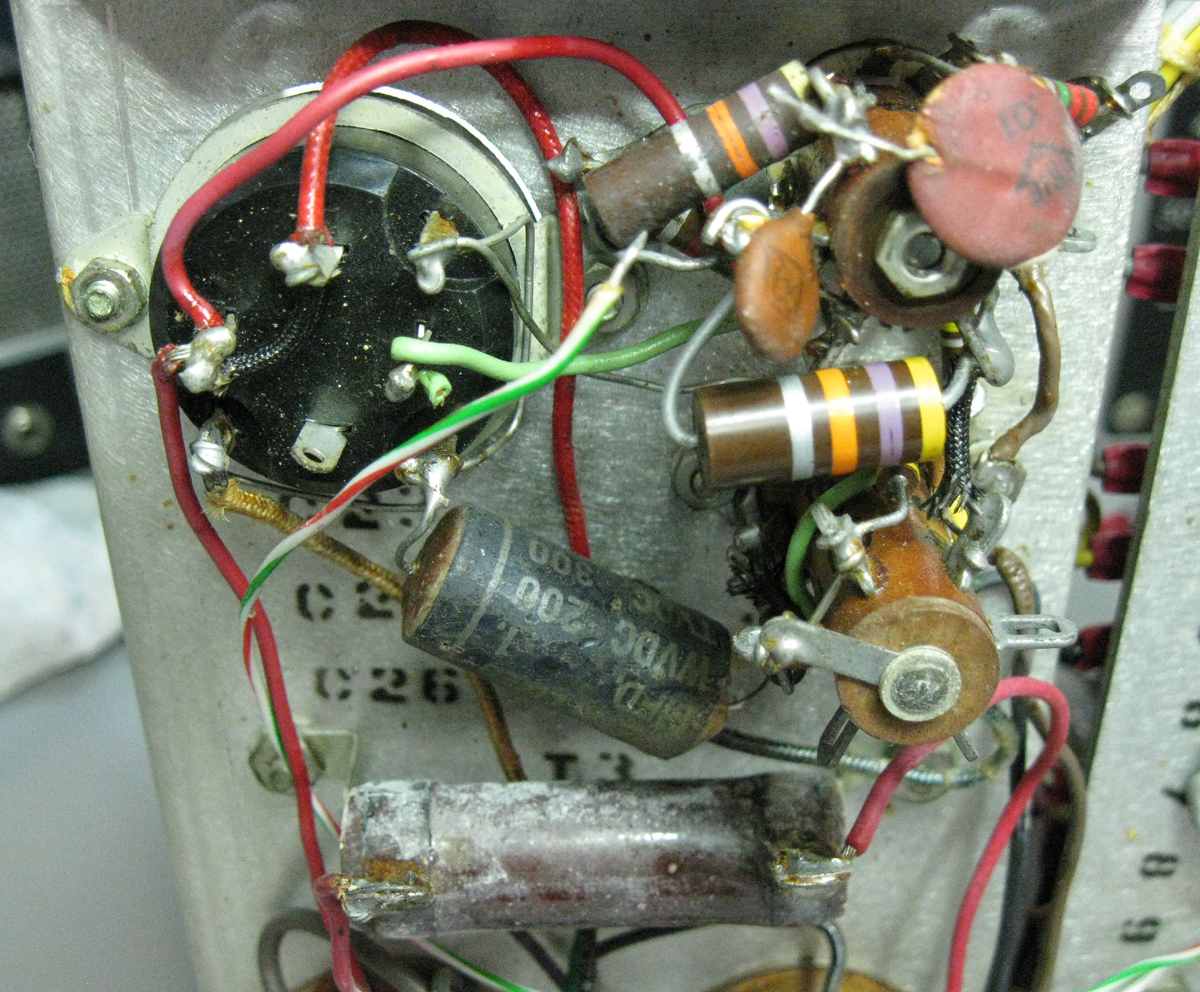
Below is an image of the underside of the audio stages and a black PIO cap I replaced and the Vishay polypropylene cap I replaced it with.
Electrolytic caps should also always be replaced. These degrade over time, most often from a lack of use, but also from a limited useful life span. A few things to consider, while many say you should always increase the capacitance value a significant amount, this is not good advice. In power supplies, assuming there little hum with the orignal values when the radio was new, adding extra capcitance is not going to improve on filtering already sufficient. As far as regulation, most of these older radios use choke input filtering, which takes care of regulation much better than capcitive input. Additionally the more you increase the capcitance in a power supply the higher the resulting DC voltage on the output of the supply. Couple this with the fact that inrush currents to charge that higher capcitance increases substancially, this puts undue extra stress on old power transformer and chokes in the supply when power is applied. So I always recommend using the same or only slightly higher capacitance values, especially in the supplies. Now what you should increase is the voltage rating. Double or tripling this is a good thing and improves overall reliability. Usually at least twice (or more) the working voltage in the circuit is best.
All text and images contained herein are under strict copyright.
Reprinting or publication in any medium is not allowed without express written consent of the author.
© Copyright 2012 John LeVasseur