|
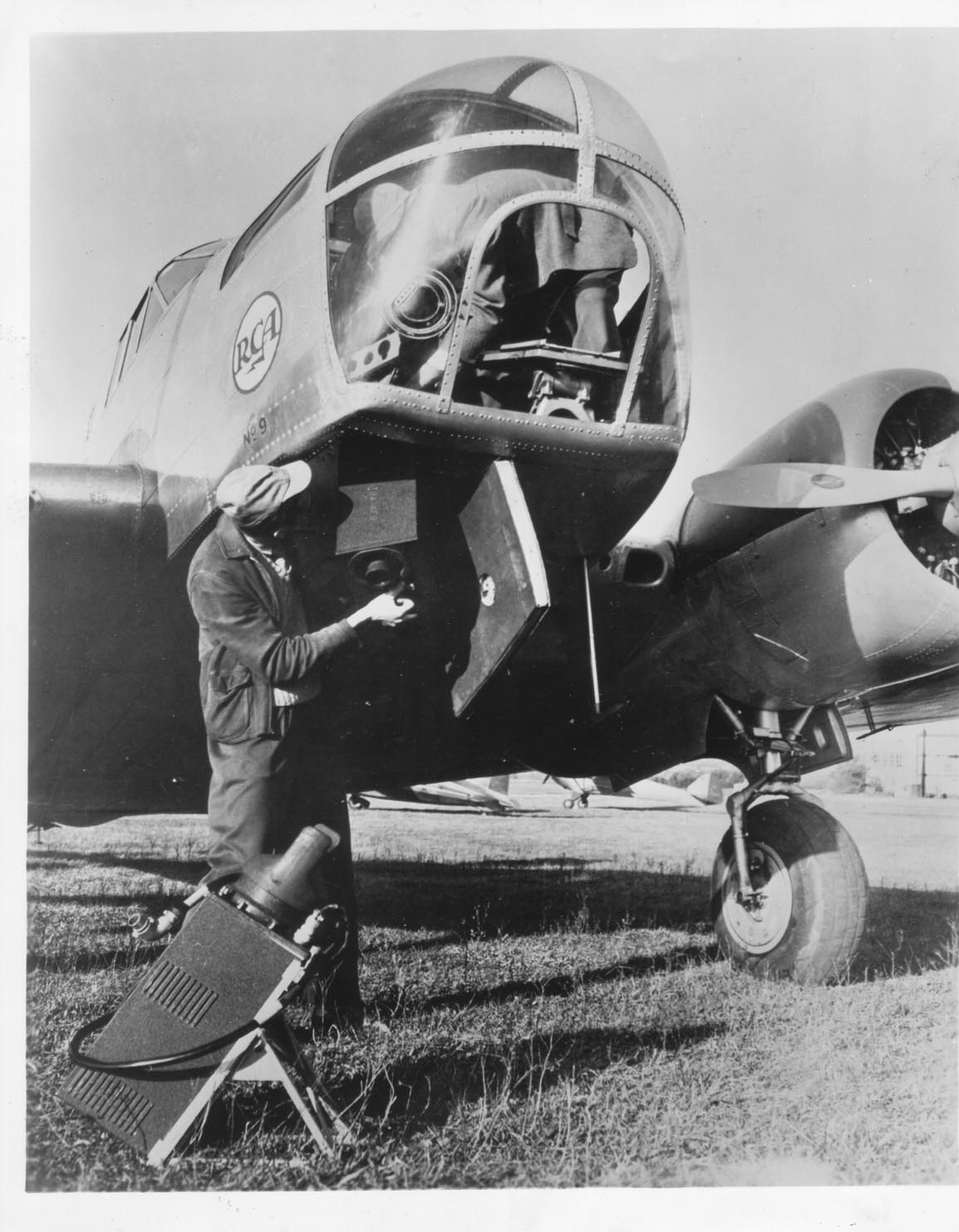
| PROTOTYPE BLOCK 1 CAMERA / TRANSMITTER - 1940 |
Victor Amateur Radio Association
Project Block | Project Mimo | Project Ring | Developmental | Test Equipment | Documentation
This history of Military Television Equipment built by RCA is
provided by Maurice Schechter,
Retired Chief Engineer of Duart Film & Video in New
York City.
He can be reached by e-mail:
Maurice Schechter
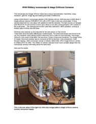
The latest presentation and demonstration of WWII Military Television Systems by Maurice Schechter was at the New Jersey Museum, InfoAge Science Center, during the WWII weekend at the museum in the summer of 2014. In addition to a historical presentation, the equipment was set up again.
New for this event
is the entire presentation and demonstration, which is online in HD at:
InfoAge Youtube Web site
Due to be published in Fall 2015 by MIT Press is a detailed historical reference book, Unmanned Systems: of World Wars I & II, from H.R. Evert. This book will cover the unmanned weapons development during and between the wars. The use of television in these weapons is extensively covered. Maurice Schechter is an historical contributor on the television and weapons system used.
A Block 1 receiver was set up for a New York Times story at the oldest electronic surplus store in New York City, Leeds Radio, in 2011.
An extensive monograph, published in 2011, Missiles of the German Luftwaffe and the United States with television directing in World War II, by Gunter Wiechmann, covers the development of television in Germany and the United States from 1936 to 1945, first as a means of communications, then for use in guided missiles. The technical details of both countrys' technology are covered with many photos and documents. The Maurice Schechter collection is featured, and he contributed as a historical advisor. 497 pages. Hardcover. In German Only.
See Maurice's presentation at the Early Television Museum, on 04-06 May 2007.
See Maurice's photos from the IEEE Seminar on RCA's military television development at the former David Sarnoff Library at Princeton, NJ, on 14 May 2004 (note: the library has closed, and the collection transferred to the Hagley Museum).
See Maurice's photos from the Military Radio Collector’s Association (MRCA) meet on 06 Sept 2003.
Project Block |
Development work on the first block began in 1940. The prototype and first developmental Block 1 cameras used the commercial 1848 iconoscopes. Production block cameras used the 1846 iconoscope. It was lower cost to produce then the 1848. It had a simplified design and used a less then perfect optical window.
Scanning rates were set as standard from the beginning of Block. All block systems from all the manufacturers conformed to the standard: 14,000 Hz horizontal rate, 40 frames per second, non-interlaced, 350 vertical scanning lines.
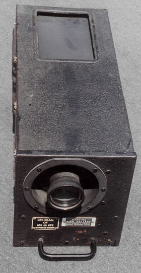
The ATE, ATF, ATG, and ATH television camera/transmitter series is known as Block 1. The camera and transmitter are housed in a single case. The sets consists of four fixed frequencies, 78, 90, 102, and 114 MHz. The channels are 9 mc wide due to the use of double sideband transmission. The RF power is 15 watts. The pickup tube is an 1846 iconoscope and the output tube an 829. The input voltage is 12.5 VDC. The components to the system are the CRV-59AAA to AAD camera transmitter, CRV-21ABY dynamotor, CRV-66ACS to ACV antenna, and CRV-60AAR monitor.
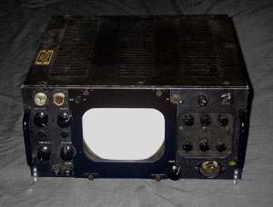
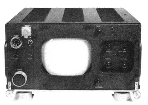
The ARE, ARF, ARG, and ARH sets are matching receiver/displays for the accompanying camera/transmitters. The receivers are fixed frequency, complementary to the transmitter, with a self-contained dynamotor and 7’’ green phosphor CRT. The input voltage is 25 VDC. The components to the set are the CRV-46ABP to ABS receiver, CRV-23ACR voltage control unit, CRV-66ACO to ACR, and CRV-66ADV to ADY antenna.
The Signal Corps version of the camera/transmitter is SCR-549-T1, T2. The receiver is the SCR-550-T1, T2. The Army Air Force sets are similar to the Navy sets except for slight modifications of design.
Contract date 1942.
|
|
| PROTOTYPE BLOCK 1 CAMERA / TRANSMITTER - 1940 |
 |
 |
| CRV-59AAC AIRCRAFT RADIO TRANSMITTER | CRV-21ABY DYNAMOTOR |
|
|
|
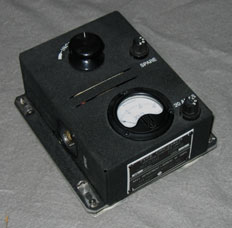
| CRV-46ABP AIRCRAFT RADIO RECEIVER | CRV-23ACR VOLTAGE CONTROL |
 |
 |
| MODIFIED CRV-59AAB WITH SYNC UNIT | ARMY SCR-549-T1, MAY 1941 |
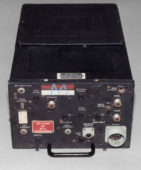
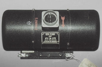
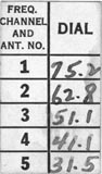
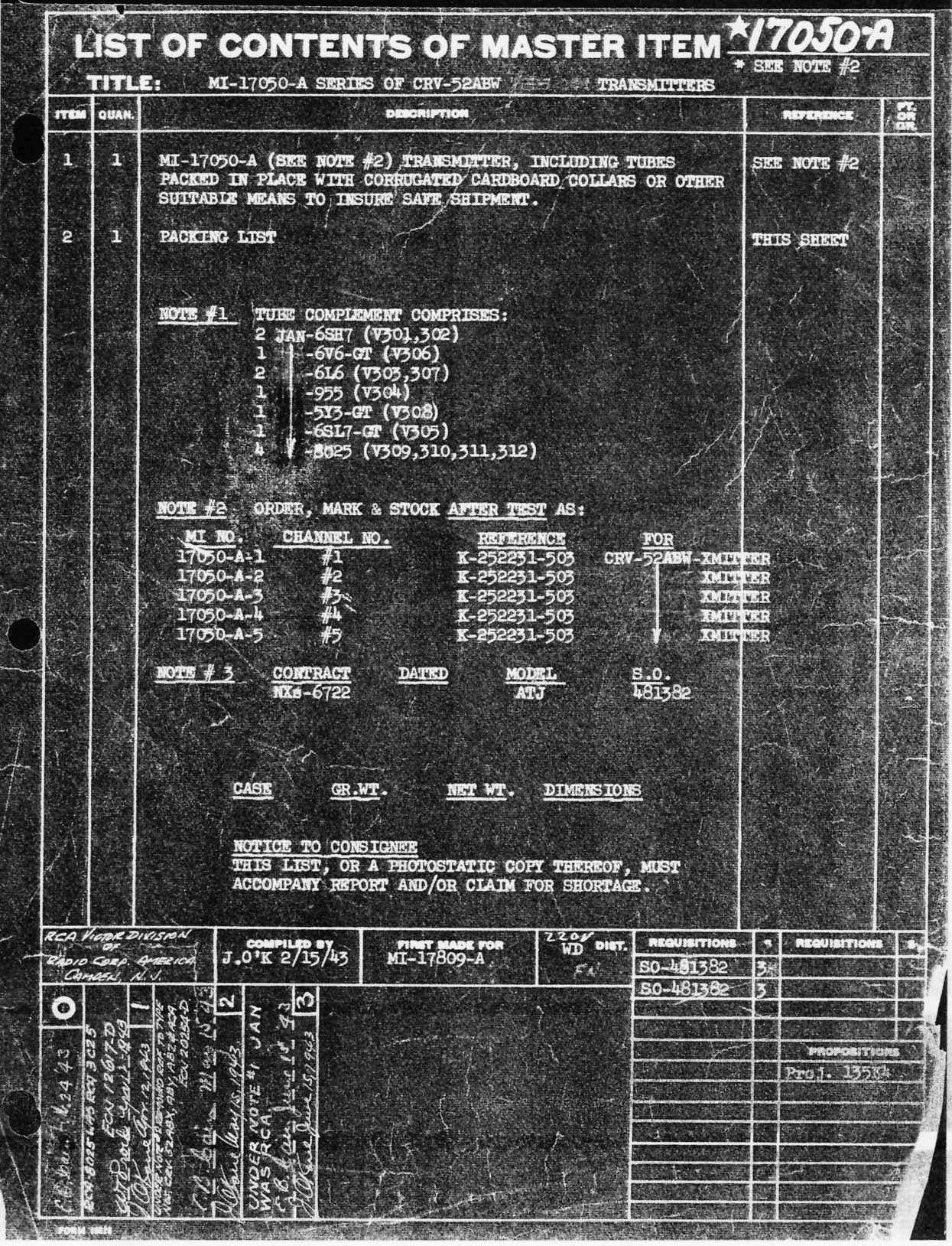
The ATJ set is known as Block 3, the first in a series that was refined during and after the war. The set is an improvement over the Block 1 sets. The camera and transmitter are separate units and improved. The transmitter is tunable to five different frequencies from 264 to 312 MHz, each 9 mc wide. The pickup tube is an 1846 iconoscope and the output tubes are 8025’s. The RF output power is 15 Watts. Input voltage is 27.5 VDC. The set components are the CRV-59AAE (BC-1211) camera; CRV-52ACA, ABW, ABX, ABY and ABZ (BC-1212) transmitters; (SW-219) remote start switch; CEK-21981 (DM-56) dynamotor; CRV-53AAB (JB-101) junction box; CRV-66AED to AEH (AN-142 to AN-146) antenna; CRV-60ABK (BC-1214) monitor; and CRV-60058 (I-206) test meter. Each of the five transmitters are preset to channels 1 to 5.
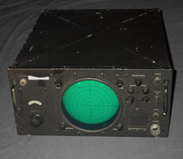
The ARJ set is the matching receiver to the ATJ transmitting set. The receiver is tunable to five channels in the 300 MHz band. The set has a self-contained dynamotor and 7” green phosphor CRT. Input voltage is 28.6 VDC. The components to the set are the CRV-46ACC (BC-1213) receiver, CRV-66ADT (AN-133) antenna, light hood CRV-10175 and CRV-60ABK (BC-1214) monitor.
The Signal Corps version of the transmitting set is SCR-549-T3, -A. The receiver is the SCR-550-T3, -A.
Contract date 1943.
 |
 |
 |
 |
| CRV-59AAE | CRV-52ABW TRANSMITTER | CEK-21981 DYNAMOTOR | AN-146 ANTENNA |
 |
 |
 |
 |
 |
| CRV-46AAC RECEIVER | CRV-66ADT ANTENNA | LIGHT HOOD | CRV-60ABK MONITOR |
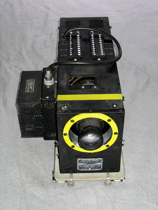
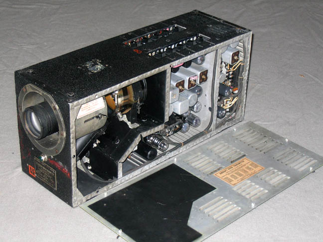
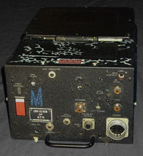
The ATK set is known as Block 3B. The major changes from the ATJ included improved sweep oscillators in the camera and stability improvements to the transmitter. The transmitter is tunable to 10 channels from 264 to 372 MHz. The input voltage is 28.6 VDC. The components to the system are the CRV-59AAE camera; CRV-52ACB transmitter; CEK-21981 or CC-21981 dynamotor; CRV-53AAB junction box; and CRV-66AFX to AGB, AEJ to AEN antenna.
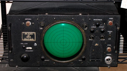
The ARK set is the matching receiver to both the ATJ and ATK transmitting sets. The major changes from the ARK are the improved RF and IF stages. The receiver is tunable to ten 8 MHz channels, separated by 12 MHz in the 300 MHz band. The set has a self-contained dynamotor and 7” green phosphor CRT. The input voltage is 28.6 VDC. The components to the system are the CRV-46ACD receiver; CRV-66ADT, AFW and ADU antenna; CRV-60ABK monitor; CRV-10175 monitor light shield; and CRV-10173 receiver light shield.
RCA subcontracted part of the production run to Farnsworth Television (CFN), which also produced the ATK and ARK sets.
Contract date late 1943.
 |
 |
|
 |
| CRV-59AAE | CRV-52ACB TRANSMITTER | TEST METER | CRV-66AGB ANTENNA |
 |
 |
||
| CRV-46ACD RECEIVER | CRV-66AFW ANTENNA | ||
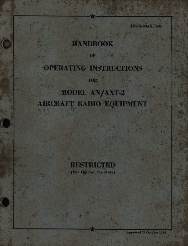
Under the new contract, the nomenclature was changed to the AN nomenclature system and further improvements were made.
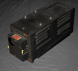
AN/AXT-2 is the transmitting set. The camera, PH-522/AXT-2, is an improved CRV-59AAE with a solenoid-controlled haze filter. The transmitter is the T-61/AXT-2, which is the same as CRV-52ACB. The junction box, J-60/AXT-2, is the same as CRV-53AAB. The dynamotor is the DY-25/AXT-2. The antennas are the same as the ATK, and the remote switch box is the SA-34/AXT-2.
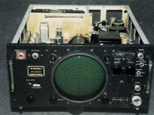
AN/AXR-1 is the receiving set. The receiver is the R-68/AXR-1, which is the same as the CRV-46ACD except for the addition of 11 enemy destructors. The antennas are the same as the ARK. The monitor is the ID-66/AXR-1, which is the same as CRV-60ABK except for the addition of four enemy destructors.
This set was built by RCA and Farnsworth Radio & Television.
Contract date 1944.
 |
 |
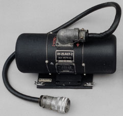 |
| PH-522/AXT-2 CONVERSION UNIT | J-60/AXT-2 JUNCTION BOX | DY-25/AXT-2 DYNAMOTOR |
 |
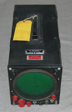 |
| R-68/AXR-1 RECEIVER | ID66/AXR-1 MONITOR |
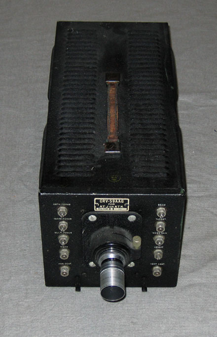
This contract was to take advantage of the new image orthicon technology for the cameras. Two models were built. The first design, the CRV-59AAG, used the first production image orthicon tube, the LM-15.
Contract date 1944.
The next generation camera, PH-548/AXT-2A, used the improved 2P21 image orthicon. Both of these cameras were interchangeable with ATJ and ATK equipment. The AN/AXT-2A used the same transmitter, dynamotor, junction box, and antennas as the AN/AXT-2, with the addition of the PH-548/AXT-2A camera.
Contract date 1945.
The K-896681 image orthicon camera is an improved version of the PH-548/AXT-2A. Using the same 2P21, the internal power supply, deflection, video amplifier, and blanking circuits were improved. A lens shutter was added, like the PH-522/AXT-2 iconoscope camera.
Contract date April 1945.
 |
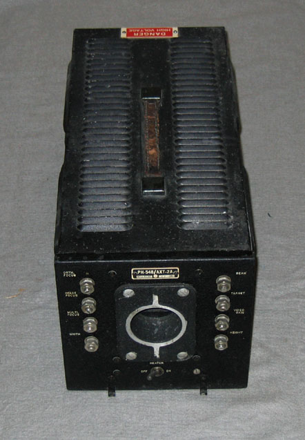 |
| CRV-59AAG | PH-548/AXT-2A |
After the war, the AXT-2 camera was modified for use in observation and telemetry applications. One such application was on the jet-propelled Bell YP-59B aircraft. Two cameras were connected to a relay unit feeding a single transmitter. The guidance aircraft could remotely switch from a display of the instrument panel to the horizon.
The set is the AN/AXT-3. Equipment is the PH-565/AXT-3 camera with flood light package, PH-569/AXT-3 camera, T-61A/AXT-2 transmitter, AT-126/AP stub antenna, AS-425/U & AS-426/U yagi antenna, and RE-26/AXT-3 relay unit. The rest of the components are the AXT-2.
Contract date 1945 to about 1954.
 |
Once production of the Block 3 systems were under way, new uses for the equipment were developed. One such use was for the Navy in Project Wolf. In this project, airplane wing stresses were studied by diving pilotless, television-equipped airplanes to earth at great speeds. Compact Block equipment was designed for the task. The Block 3 camera was divided in half, separating the iconoscope from the drive electronics. Transmitting frequencies were tunable to 190, 202 or 214 MHz. Block 3A receivers were modified for compact block frequencies.
 |
| COMPACT BLOCK CAMERA, CAMERA CONTROL UNIT & TRANSMITTER |
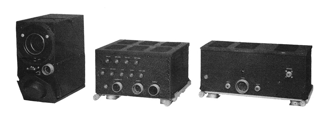
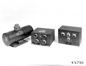
Another series of small block equipment was produced. This was a form of closed circuit television, were the signal was not transmitted over the air. Using parts of Block 1 designs, a small Iconoscope camera and monitor were developed. The system used one set of scanning electronics, located in the monitor, to drive the camera and monitor. This substantially reduced the size and weight of the camera.
Uses of the equipment were wide. Cameras were placed at gun mounts on larger naval aircraft, creating television gun sights. On aircraft carriers, cruisers, and battleships, compact cameras were used to televise the plotting board throughout the ship. At DuPont's Hanford complex in Washington State, where plutonium production took place for the first atomic bomb, these cameras were used to monitor the crane that loaded the atomic reactor.
 |
 |
 |
| ICONOSCOPE CAMERA | MONITOR | COMPLETE SYSTEM |
Under a National Defense Research Committee (NDRC) development contract in 1943, NBC, subcontracting for RCA, developed a narrowband system of television to be adapted to telemetering the transmission of aircraft instrumentation from pilotless, experimental, or radio controlled planes to the control plane or ground. The 10 fps rate and 300 lines reduced the bandwidth to 750 kHz. A 2" orthicon tube and long-persistence display was used to reduce flicker. The transmitter used a 829 tube to produce 15 watts. The camera used the earliest implementation of a photocell-controlled automatic iris. Orthicons had a tendency of runaway blooming if the light level was not controlled well. Later image orthicons did not have this problem. Both photos are from the Denson Electronics catalog in Rockville, Connecticut. Denson sold many military TV cameras in the day.
 |
 |
| BLOCK MINI ORTHICON CAMERA | |
Project Mimo |
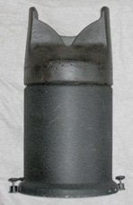
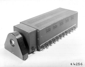
MIMO is an acronym for Miniature Image Orthicon. During the war, advances in tube miniaturization made project MIMO possible. The project entailed the use of a medium-angle guided bomb-type missile called ROC, with television guidance. The system consisted of a small cylindrical camera unit placed in the nose of the missile, a small transmitter, power supply, and a dipole antenna. The complete system weighed 50 pounds, and had a power of eight watts in the 264 to 372 MHz range. The designation is the AN/AXT-7.
Contract date early 1945.
 |
Project Ring |
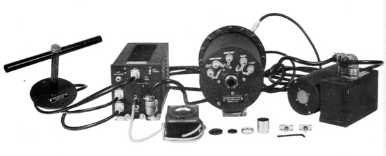
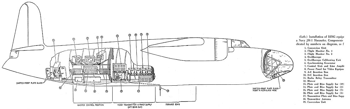
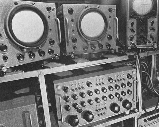
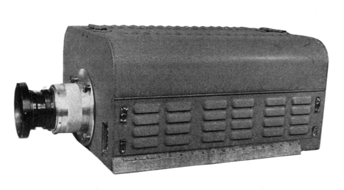
This equipment was developed for long-range, high-altitude reconnaissance operation. Designed for attended operation, weight and complexity considerations were secondary to the production of high-definition television pictures. The project was a joint development between NBC and RCA. The system produced a greater resolution image than NTSC. Specifications were 20 fps interlaced, 567 vertical lines, and 500 horizontal resolution lines.
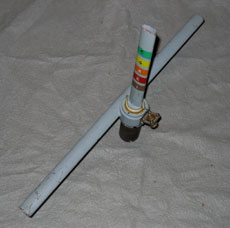
Two cameras were developed using an image orthicon and a developmental multiplier orthicon, PH-536/AXS-1 and PH-537/AXS-1. The transmitter operated on 90 to 102 MHz with a peak power of 1400 watts. Range was 200 miles at 22,500 ft. The transmitting set is the AN/AXS-1 and the receiving set is the AN/UXR-2.
Contract date 1944.
 |
 |
 |
|
| PH-536/AXS-1 IMAGE ORTHICON CAMERA | CONTROL UNITS | 1KW, 100 MC TRANSMITTER |
|
|
|
| 1.4 KW TRANSMITTER AND AMPLIFIER | 1.4 KW POWER SUPPLIES |
 |
 |
| PH-537/AXS-1 MULTIPLIER ORTHICON | ID-86/UXR-2 12" VIEWING MONITOR |
Developmental Cameras and Equipment |
These cameras were built to test ideas for improving design and picture quality at RCA Labs (Princeton, NJ). Some of the cameras evolved into the production versions above. Numbered photos are courtesy the David Sarnoff Library.
 |
 |
 |
| Super image orthicon camera | Super image orthicon camera bottom | Image orthicon camera with Schmidt optics |
|
|
|
| FINAL DEVELOPMENTAL Image orthicon camera | Image orthicon camera rear |
 |
 |
 |
| Early Mimo camera | Mimo dynamotor on right | Mimo transmitter on right |
 |
|
| ORTHICON BLOCK CAMERA | BLOCK 3-BB TRANSMITTER |
SPECIAL TEST EQUIPMENT |
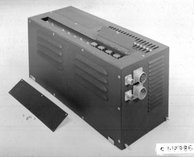
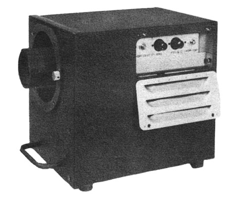
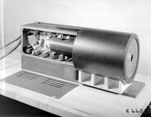
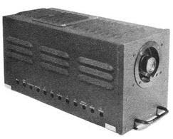
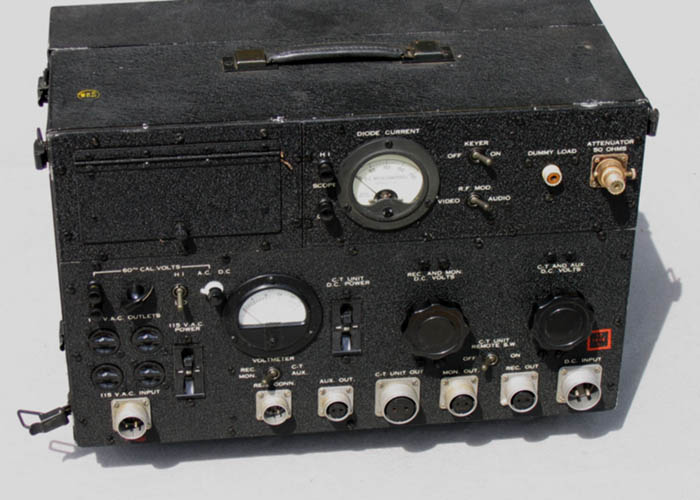
Shortly after Block 1 went into field testing, the need arose to have a reliable way to set up and test the cameras and transmitters in the field. Two major pieces of equipment were developed. First is the Light Projector. A lightbox with daylight florescent lamps illuminated a test pattern side. A fixed lens projected the image through the camera lens onto the iconoscope mosaic. The projector and camera lens matched, allowing the focus of the camera to be set for infinity.
A combination test set supplied all the power requirements to camera, provided a dummy load for the transmitter, and measured depth of modulation. These test sets would work with either Block 1 and 3.
 |
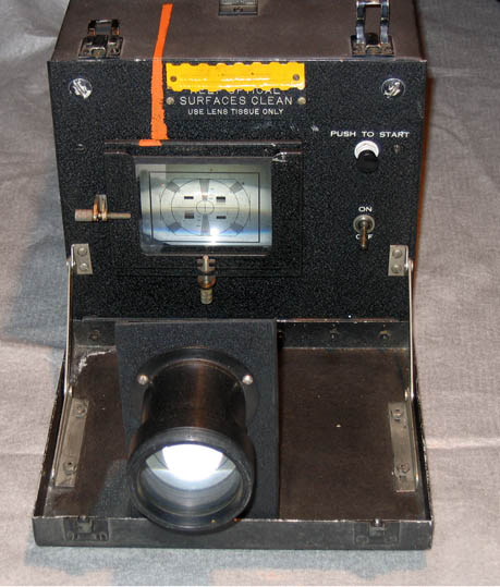 |
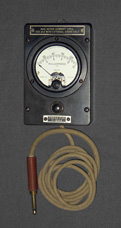
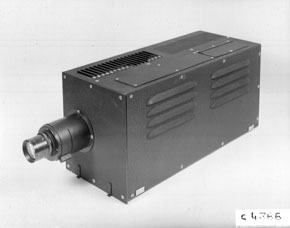
| I-231 TEST SET | I-232 (TS-93AX) PROJECTOR |
DOCUMENTATION & PHOTOS |
 |
 |
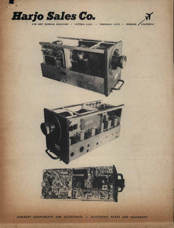 |
| AN/AXT-2 OP MANUAL CAME IN MASTER CRATE | ATJ TRANSMITTER PACKING SLIP | SURPLUS STORE SELLING BLOCK |
 |
 |
| CLICK FOR LARGER PICTURE |
 |
||
| Military Iconoscope & Image Orthicon Comparison Report |
|
Page Maintained by Pete Greene, N2LVI Contact: Pete Greene, N2LVI
Last Updated 10 Dec 2015 |
e-mailed to Maurice Schechter Photos are from the Maurice Schechter Collection except as otherwise noted. Usage of images and text are permitted with proper credit to the author and VARA |