A 30M QRP CW Transceiver built Manhattan Style

Below are details and pictures related to the construction of my SW30++ transceiver. Early in the millennium a group was formed on the QRP-L reflector to promote building equipment using the "Manhattan" style of construction. The effort was called MH101 for Manhattan 101. The idea was to build a 30M transceiver based on the K1SWL SW 30 design. With related discussion on QRP-L, a number of hams collected parts and began to build this rig.
Most hams in the group built the VFO but only a few went on to build the complete transceiver. QRP-L activity related to the project dwindled. When it looked like activity on the project had come to a halt, I started creating a circuit layout for the entire rig using PCB CAD software. I also worked on some of the modifications I wanted to build into it, namely RIT, an IF amp, AGC and a Keyer/AFA. This page documents the process I went through to build the rig. Hopefully it will inspire someone to build this rig or another one using this versatile and RF friendly construction technique.
Board Machining and Layout
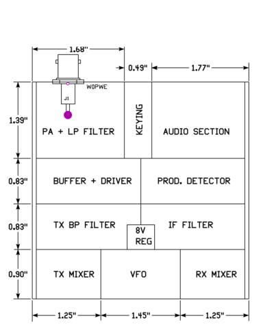
I decided to build my MH101 rig in an enclosure identical to the one I used for my SST-20, but I wanted to keep the layout roughly the same as the one K7QO developed for the MH101 project. His board is 12.0cm by 7.5cm or 90 square cm. My board is 10cm square but a narrow strip down each side is used by the card guides in the enclosure, so my total area is 97 square cm. The total area is therfore adequate but I had to re-adjust the size of each repsective section to account for the different aspect ratio. The drawing above reflects these adjustments and each section has approximately the same area as it had in Chuck's layout.
The pictures below show the process of cutting the board to size so that it will fit in the enclosure. I use a Sherline lathe with milling attachment to cut the board because it produces nice square edges that slide in the card guides well. The enclosure is a Schroff subrack module. The extruded tube is half it's original length and the front panel is cut down.
 Milling the board to size Milling the board to size |
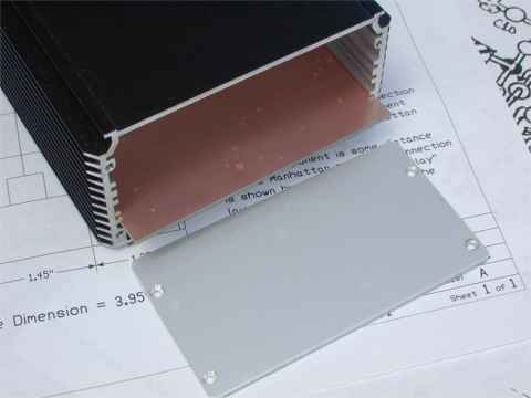 Test fit board in enclosure Test fit board in enclosure |
Component Placement

The picture above is a layout I developed for the SW30++ transceiver. It incorporates several enhancements that I wanted the rig to have. Those are an IF amplifier, a 4 pole filter designed by K8IQY, and my homegrown Keyer/AFA. I believe the layout is useful to others wishing to build the rig and variations of it. For example, the section that contains the Keyer/AFA could be left empty or a commercial device such as the KC1 could be installed in that space. A FreqMite or keyer such as the TICK or K1EL could also occupy that space. When I built the rig I realized the IF amplifier was not needed so that space is available for expansion or additional features. The K8IQY filter is an easy to implement enhancement but if one wanted to use the original SW30 filter, the component layout in that area could be modified accordingly. The board is designed to fit in the same enclosure I used for my SST-20.
The picture above is a low resolution image of the actual layout. It is intended to convey only the general idea of the design. Anyone wishing to build a rig based on this layout should e-mail me at the link below and I will send a high resolution image. It also contains a key and notes that are very important to the construction and layout.
Building the VFO Section
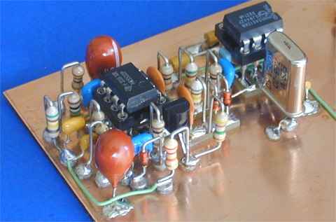
The oscillator went together pretty easily. There seemed to be plenty of room on the board, it generates a nice sine wave, and appeared to be stable based on limited testing.
Before I started building I went to the hardware store, purchased a bottle of Tarn-X and cleaned the board as discussed in the MH101 group. The board became nice and bright with little effort. In an effort to keep it that way during construction I masked off all but the VFO section with Scotch #2090 blue masking tape and began soldering.
My oscillator seemed to be performing about the same as others reported on QRP-L. Approximately800mv p-p output is available for the receiver mixer and the frequency of oscillation is about 2.52 Mhz with no tuning voltage applied to the varactor.
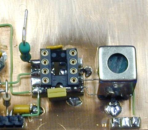
 VFO back side view VFO back side view |
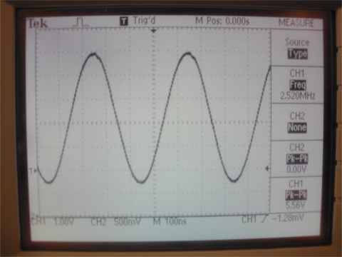 VFO output sine wave VFO output sine wave |
Building the First Mixer
Except for the layout design, I did no actual construction on this project for several months after building the oscillator. During that time the masking tape adhered to the board and had to be scraped off. This left a mess behind that had to be cleaned with acetone and steel wool. I won't try that again and I have decided that a few fingerprints on the board will only personalize it and give it unique character.
Construction of the first mixer went about as expected. I followed the layout closely and had no trouble making everything fit. The IC is mounted on special 8 pin pads that I made up using CAD software and DynaArt. I usually glue the pad in place then connect as much of the surrounding circuitry as possible. The socket is soldered in near the end of the process. Artwork for the 8 pin pads and details about making them are given on my Homebrew page.
Crystal Filter Construction and Verification

Jim Kortge, K8IQY designed a 4 pole crystal filter as an enhancement to the original SW30 design. The 4 pole design offered better selectivity than the original 3 pole design and it included L network impedance matching at the input and output. I decided it was a modification worthy of a place in my SW30++.
I had purchased a set of crystals that had been matched by parallel resonant frequency. It seems however that common practice is to select crystals for filters based on their series resonant frequency. To accomplish this I relied on a device I had built when I selected crystals for my SST filter, a Colpitts oscillator with very large feedback capacitors. K8IQY mentions this method in his article on building the IA-QRP-10 transceiver and suggested that it can produce a result that is close to the series resonant frequency. Further details can be found on my Homebrew page. While not perfect, this method did produce a nice filter for my SST so I decided to try it again. Tested this way, my set of 6 crystals had a spread of 65hz. The 4 crystals I used for the filter were within a spread of 37hz. While I would like them to all be within a few hz of each other, the 37hz spread fits within the rule of thumb that states the spread must be less than 10% of the desired filter bandwidth. Here is the measured bandwidth of the filter as constructed:
| Output |
Bandwidth |
| -3db |
520hz |
| -6db |
660hz |
| -12db |
840hz |
| -20db |
1160hz |
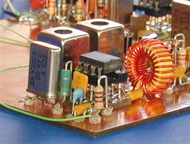
Construction was pretty straight forward. As shown below, I used rectangular pads to simplify construction.
 Rectangular Pads Rectangular Pads |
 Completed Crystal Filter Completed Crystal Filter |
Building the Product Detector and a Functional Test

There isn't too much to be said about the product detector. I mounted the ground end of the crystal on a pad and then soldered a wire from there to ground. With this arrangement I can easily add a capacitor from the crystal to ground if necessary to pull the crystal frequency around.
After this stage was built I thought it would be interesting to see if the receiver was working up to this point. Connecting a St. Louis audio amp to the product detector provided just enough audio amplification to check things out. When an antenna was connected to the input I could hear 30 Meter signals so I knew the receiver is functional to this point.
Building the Audio Section and Receiving On Air Signals
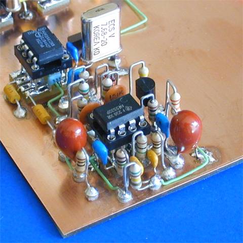
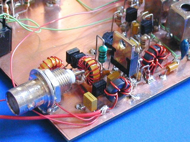
In this stage of the construction process I built the audio section and then connected the rig to the station antenna to see how it performed on the air. The photo above shows the audio section in the foreground and the product detector behind it. As you can see, this section has the most components of any section so far. When doing a section like this one it really helps to draw a layout first.
After the audio section was built but before I connected it to the product detector, I connected my audio oscillator to the input through a small audio transformer. Sweeping the audio range indicated a nice bandpass response, but the center frequency was about 900hz. A QRP-L post earlier by Bob, W3CD indicated similar results. He changed C26 from .0022ufd to .0033ufd and moved it to 700hz. I made that change and my peak moved to 700hz as well. That frequency seems to match my ears and the peak from the product detector a little better.
With the audio tweaked I connected the product detector and decided to try the receiver on the air. Wow, 30 meters was hot that night! I copied all kinds of DX stations from Europe to South Africa. The receiver sounded great and the K8IQY IF filter is a pleasure to use. This receiver has plenty of gain and I see no need for the IF amplifier I had planned to build in. Darn, I spent a lot of time tweaking that amplifier with SPICE and on the breadboard. Now I don't need it and I have a big empty space in the receiver strip where it was going to go. Maybe an AGC circuit could fill that hole?
Below are pictures of the audio section and the complete receiver
 Audio Section Audio Section |
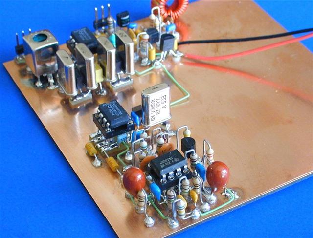 Complete Receiver Complete Receiver |
The Transmit Mixer and Band Pass Filter
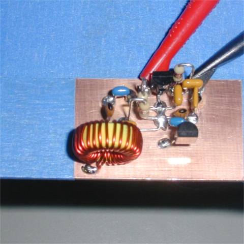
After hearing signals in the receiver I am excited about finishing the transmitter side so I can put this rig on the air. The transmit mixer uses another SA612 IC and a pair of 10.7 Mhz IF cans to clean up the output. The output looks good on the scope and should have enough signal to adequately drive the next stage.
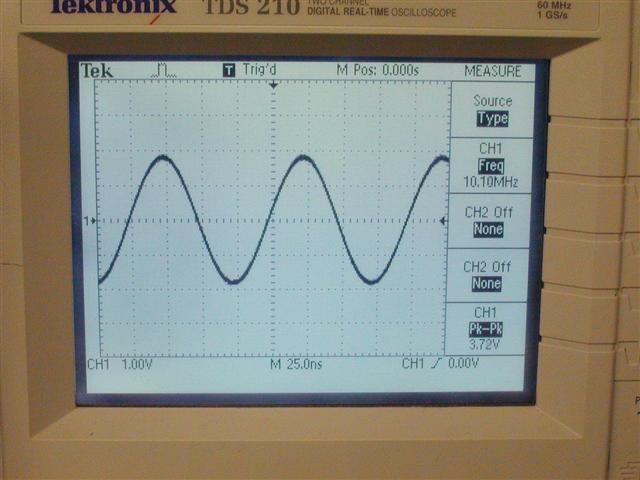 Output of the Band Pass Filter Output of the Band Pass Filter |
 Top View of Xmit Mixer & BPF Top View of Xmit Mixer & BPF |
Transmit Buffer and Final Amplifier
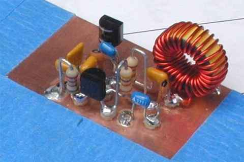
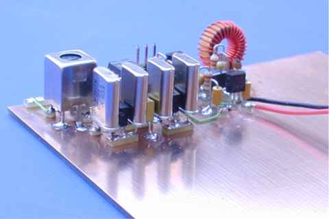
The transmit buffer amp and keying circuits sit just this side of the two band pass filter cans. That section went together fast and the output looked good so I built up the amp and low pass filter. One of the fellows in the MH101 group did a group buy on C2078 transistors which make a great final for this rig. It runs a solid 3 watts output and does not require a heatsink.
With the transmitter finished all I had to do was hook up a 10 turn pot for tuning, another pot for RF gain, jacks for headphones, keyer and power and I was ready to try it out on the air. My first qso with the rig was with Jim - K8IQY in Fenton, MI. My second qso with the rig (and first DX) came a little later that evening and it was with LZ1CY in Bulgaria. Several weeks of playing with it in this configuration followed before I finally took it back to the bench for some enhancements.
 Buffer and Final Amplifiers Buffer and Final Amplifiers |
 Patched Together and On the Air Patched Together and On the Air |
A Few Enhancements
With the rig operational and proven on the air it was time to add a few features to make it more enjoyable to use - namely Automatic Gain Control (AGC), Receiver Incremental Tuning (RIT), and the Audio Frequency Annunciator with Keyer.
The ACG Circuit
One of the awesome features of Wayne Burdick's SST design is a clever but very simple AGC scheme. With only 3 components (LED, electrolytic capacitor and a choke) a very effective AGC can be had. When the signal is large enough, negative half cycles of the audio output are applied to the electrolytic capacitor via the LED which reduces the bias on the mixer input stage and therefore reduces the gain. If the LED is brought to the front panel it even provides a relative signal strength indicator. The audio stage of this rig is built around a dual op-amp rather than the LM385 as used in the SST. The op amp didn't like feeding the AGC circuit directly but a 1K resistor in series with the LED proved effective. Good AGC action was noted with on-air signals and it took an input of about -35dbm at the antenna to produce clipping of the audio output. The space I had reserved for the IF amp provided plenty of real estate for the AGC components.
Receiver Incremental Tuning
RIT makes using a little rig like this a lot more enjoyable to use and it provides a basic means of operating split when those DX stations show up on 30M. The RIT circuit uses a second varactor diode to provide the incremental tuning and a 2N7000 mosfet to zero out the tuning pot on transmit. A center detent potentiometer was used for the control so it is easy to get back to zero. A little space was found by the VFO inductor for the RIT components.
Keyer and Audio Frequency Annunciator
The Keyer/AFA is a duplicate of the one I built for my SST-20 and it is described on the Keyer/AFA page.
Home |
Radio Projects |
Antenna Projects |
Homebrew Info |
Email
|