A Full Featured Keyer with Frequency Counter

Introduction
To make my QRP rigs a little easier to use (especially mobile and in the field) I programmed a PIC16F84 microcontroller to serve as a keyer and a frequency counter with Audio Frequency Annunciator (AFA). In other words, a keyer and Morse code frequency readout.
Here is a list of the features I was striving for when I started this project:
| Feature |
Description |
| Memories |
Three pre-programmed and two that are user entered |
| Speed |
Quick adjust with pushbutton and paddle inputs |
| Sidetone |
Internally generated, can be enabled or disabled |
| Callsign |
Hard coded or user-defined, saved in eeprom |
| Iambic |
Both A and B modes supported |
| Key Modes |
Straight key,iambic,and tune modes |
| Speed rpt |
Replies with current speed setting in WPM |
| Paddle Swap |
Exchange dit and dah paddles |
| Autospacing |
Optional, inserts proper inter letter spacing |
| DE mode |
Optional, sends "DE callsign" when both paddles pressed |
| Freq. Range |
1 to 30 Mhz |
| Freq. Offset |
Selected at code assembly time |
| Freq. Digits |
1 to 7 Selected at code assembly time |
| Freq. Announce |
Initiated by pressing a push button switch |
The Approach
While I enjoy writing code, sometimes you find things in the public domain that make it difficult to justify writing the code yourself. Prior to starting this project I discovered some code for a great little keyer on the K1EL web site. I promptly downloaded the code (K8) and programmed a 12C509 PIC processor with it. I built that keyer into a single band rig and later built a stand alone PIC Keyer based on it. The K1EL PIC code is well written, rock solid code that yields a great keyer.
If you go to the K1EL site and look under "Free Stuff" you will see that the code is still available along with code for an improved keyer and some other neat gadgets
Keyer Code and Processor Choice
Impressed with the K8 keyer code, I decided this would be the base of my keyer/counter project. Trying to do this project with the 12C509 would be a problem because I don't have a pic emulator. Using the "burn and learn" approach (burn eprom, test, try to learn why it doesn't work, and erase eprom) with a windowed eprom part was an option but not a very good one. Also, because the K8 code uses all the 1K program memory I would have to do some serious hacking to make room for the AFA code. Many "burn and learn" cycles would no doubt be required. The best approach, given my modest set of development tools, seemed to be to port the 12C509 code to the 16F84. Not an easy task, but worth the effort it if yields a K8 like keyer in the 16F84. By the way, there is now a 16F84 version of the K8 code on the K1EL website.
Frequency Counter Code
There are plenty of good PIC frequency counter examples to follow. Several were found on the web and in the Microchip appnote library. The October 2000 QRP Quarterly had an article by WA1EDJ and AE4GX describing an AFA they built for the Georgia Sierra. It looked interesting so I e-mailed Sam, AE4GX and he sent me the source code. Their project was based on some 16F84 code that was written by Bernd Kernbaum DK3WX. I programmed a 16F84 with their code and experimented with it. It worked quite well and provided me with some good ideas. My approach was to maintain as much of the keyer functionality as possible and keep the AFA features to a minimum. For example, the number of frequency digits sent and the frequency offset (IF frequency) are configurable before assembly but not adjustable during operation. This is not a problem since the intended application is single band transceivers where those parameters are pretty well fixed.
The Development Process
My development tools consist of the following: 1.MPLAB, an assembler, debugger, integrated development package available for free from the Microchip web page. 2. PICSTART PLUS, a Development Programmer from Microchip used to burn the program into the PIC Flash memory. 3. A PIC16F84 prototype board that I built on perf board. The prototype board has a pin header that brings all the 16F84 I/O pins out where they are easily accessible. It also contains a 5 Volt regulator, pin header for external power in and out, and a reset switch. The prototype board also has enough extra space for future additions. Below are some pictures of the development tools and a copy of the schematic.
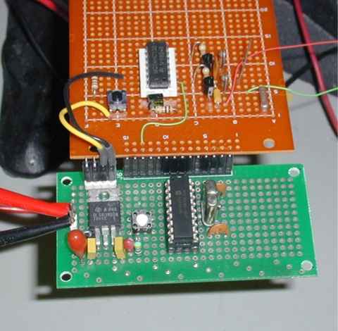 Proto Board and AFA Test Circuit Proto Board and AFA Test Circuit |
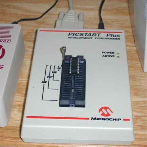 PICKSTART PLUS programming a 16F84 PICKSTART PLUS programming a 16F84 |
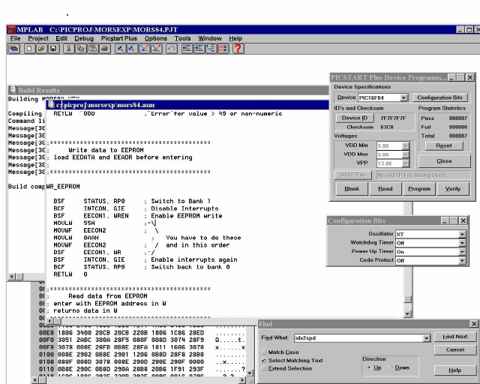 MPLAB Development Environment MPLAB Development Environment |
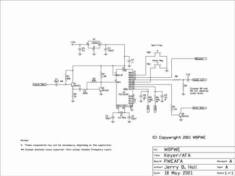 Keyer/AFA Schematic Keyer/AFA Schematic |
Progress Report
Below is a list of the steps I pursued in developing the software.
| Step |
Work Done |
| 1 |
AFA from QRP Quarterly article built and working |
| 2 |
Code ported from K8 to 16F84 |
| 3 |
Removed "Farnsworth" and "Practice" modes to gain code space |
| 4 |
Developed code to change code speed with Pushbutton and Paddle inputs |
| 5 |
Developed code to read and write to EE_PROM |
| 6 |
Speed and mode settings stored in EE_PROM |
| 7 |
Added code to output 24 bit number in Morse |
| 8 |
Removed "Speed" and associated subroutines to make room for AFA code |
| 9 |
Configured counter input. Added code to count pulses on RA4 |
| 10 |
Added code to add/subtract IF offset |
| 11 |
Fixed bug in first frequency read. Modified input circuit and RA4 levels |
| 12 |
Created Schematic Drawing |
| 13 |
Built Manhattan version in SST-20 and began testing |
Conclusion
The keyer/AFA is now standard equipment in my single band QRP rigs. There are still a few bugs in my software and there are a number of things I would like still like to do with it(like port it to a newer processor and layout a circuit board for it). Other projects are now on the front burner however so this one is probably done for now.
|