Introduction
The advantages of using the tuned loop antenna for LF reception have been described in previous articles. The signal level induced into the loop is quite low and to ensure that this level is well above the inherent noise level of the following interface amplifier, it is desirable to use a loop which has high Q to achieve a high voltage multiplication within the loop tuned circuit. There are also a number of other advantages in raising the Q such as improving rejection of strong adjacent signals which might cause cross modulation in the following mixer. However this high Q inhibits operation of the normal noise blanker installed in most receivers. Noise blankers work on impulse type noise and the aim of the system described is to provide a means to blank out this type of noise whilst still taking advantage of the feature of high Q within the loop.
In previous articles, I described a loop converter (reference 1) and a noise cancelling unit (reference 2) which operated from an auxiliary antenna to provide a cancelling signal which was mixed with the output from the loop antenna. In the following text I describe a further blanking unit, which is fed from the same auxiliary antenna and the same noise cancelling unit, but in this case, the latter operates as a tuning and gain controlled interface unit.
The System
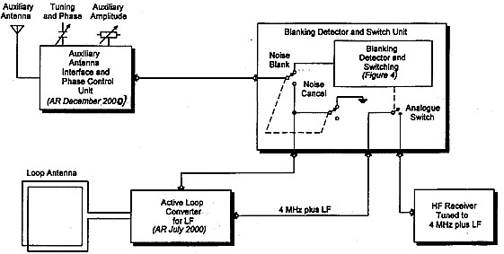
Figure 1 shows how the system is connected up. The auxiliary antenna is connected to the noise cancelling unit which controls phase and amplitude for adjusting noise cancellation. The output of this unit is fed via a switch in the blanking unit and with the switch selected for noise cancelling, the output is fed to the loop converter for mixing with the loop signal. For this switch connection, the system operates as described in reference 2.

With the switch selected for noise blanking, the noise cancel unit output is fed into the blanking detector. In this operation, the phase control is simply a tuning control and the amplitude control sets the level into the blanking detector. When triggered, the blanking detector operates a CMOS bilateral analogue switch which opens the 4 MHz loop converter output to the host HF receiver for a defined preset period.
The noise cancelling and noise blanking units are in separate metal boxes to the loop converter and the three are interconnected via BNC connector ended cords. The arrangement is how the experimental system evolved. I initially built the LF Converter with regeneration for Q control. I later thought I would try noise cancelling and later again the blanking system.
Impulse Noise & Blanking
It is interesting to observe with a CRO on what happens across a tuned circuit when energised by a short impulse. The tuned circuit is triggered into oscillation and a damped wave train is generated with each cycle decreasing in amplitude to that of the previous one. The higher the Q of the tuned circuit, the longer it takes to dissipate the energy and the longer it takes for the amplitude to fall to a given low level.
A formula derived from information in the Admiralty Handbook
gives N as follows:
N = 1 + 0.73 Q
where N = No of cycles for amplitude to fall to 10% of
initial value
and Q = Circuit Q
A sample frequency of 200 kHz is the lowest frequency for aeronautical non directional beacons and is close to the New Zealand amateur band of 165 to 190 kHz. The period of one cycle at 200 kHz is 5 microseconds. Selecting this frequency and using the above formula, figure 2 is evolved plotting time for the damped wave train to fall to 10% of its initial value verses circuit Q.

Take a good typical loop which has a Q of 200. It can be seen from the curve that for this loop, it will take more than 735 microseconds for a triggered wave to fall to a negligible value. If the effect of the impulse is to be eliminated, the received signal will have to be switched off (or blanked out) on the first cycle and remain off for a period not less than 735 microseconds.
Now lets turn to the question of how the start of blanking is initiated and how the impulse is selectively detected. The blanking system normally relies on the fact that the impulse is of higher amplitude than the signal and is of very short duration so that the blanking is triggered by this short pulse. If there is a tuned circuit in the triggering path and the Q is low, triggering occurs on the first cycle of the damped wave train generated and the second and subsequent cycles fall away rapidly in amplitude so that they don’t confuse the triggering circuit.
However, if the Q is high, the change in amplitude from cycle to cycle is very small as the decay of amplitude with time is stretched. Detecting this to operate the blanking trigger produces a stretched version of the original impulse which is unsuitable for edge triggering of the blanking switch. So to get over this problem with the high Q loop, we feed the blanking trigger from an auxiliary wire antenna via low Q tuning. We could also use an untuned noise pick up but some form of selective tuning or bandpass filter is needed, at least in the City, to stop false triggering of the blanking circuit by strong local broadcast stations and aeronautical beacons.
As it turns out, the tuning system in the unit already built for noise cancelling has quite low Q and I was able to put the unit to use, without modification, as the auxiliary antenna interface for the blanking unit.
An interesting thing is that this problem of the noise blanking system not working with the high Q loop is a characteristic of the low frequency band. As already discussed for a Q of 200 at 200 kHz, the decay period of the impulse triggered damped wave falls to 10% of its initial value in 735 microseconds. However for a Q of 200 at 2 MHz, the decay period is only 73.5 microseconds and possibly short enough to work the normal blanking circuit.
To demonstrate this theory, I tested another loop antenna, which I had made for 1.8 MHz, on two different HF transceivers with blanking fitted. The loop has a Q of around 100 and based on the above calculations would have a decay period to 10% in 41 microseconds. The blanking worked quite successfully on impulse noise with impulse repetition frequencies of 50 and 100 Hz. Operation failed for higher repetition frequencies but the blanking circuits were probably only designed to cope with power line interference at the lower frequencies. Using the same transceivers converted up from 200 kHz with my LF loop set to a similar Q, there was no way in which blanking would work.


The Blanking Unit
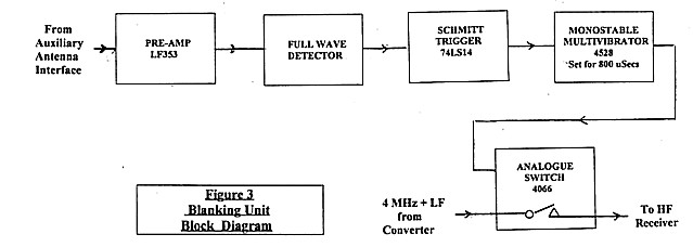
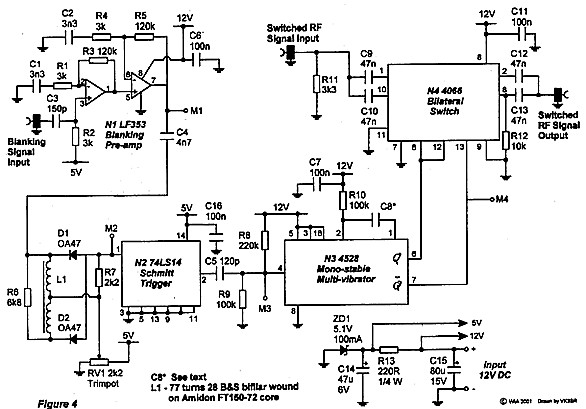
Figure 3 is a block diagram of the blanking unit. Circuit detail is shown in figure 4 and operation is as follows:
Noise signal from the auxiliary antenna interface unit is amplified by the two stage amplifier N1, a twin JFET operational amplifier package type LF353. The output of N1 is coupled to Schmitt trigger N2 via full wave rectifier circuit L1, D1, D2. The idea of the full wave circuit is to ensure that the leading edge of the first half cycle of the impulse initiated wave train triggers N2 independent of whether the first half is positive or negative. N2 (74LS14) is a TTL type of trigger requiring a 5 volt rail and this is derived from zener diode circuit ZD1, R13. The 5 volts is also used to set the operating points of amplifiers N1. I could have used a CMOS type trigger here with the 12V rail but I didn’t have one and I did have the 74LS14 on the shelf. There are 6 individual Schmitt trigger gates in the N2 package and of course 5 are spare.
The rectified output of D1-D2 produces negative going pulses and N2 bias is set by trimpot RV1 so that N2 is triggered on by the negative going signal. I found it operated nicely at 1.8V of bias.
When triggered, N2 produces a 5V step which is differentiated by C5, R8-R9 and the spike flips monostable multivibrator N3 (type 4528) to an ‘on’ state where it remains for a period determined by the values of R10 & C8. Because the output of N2 is only 5V, the setting of reference voltage at pin 4 of N3 is fairly critical and this reference is set by the ratio of the values of R8 and R9.
Of course the ‘on’ time of the multivibrator sets the blanking period and I experimented with this quite a bit. For very high loop Q, the blanking period can be advanced to around 800 microseconds. Advancing beyond this deteriorates the tonal quality of the detected audio signal as heard in the receiver. Referring to the 10% level curve of figure 2, this equates to a Q of 220. In the loop converter used, I can apply regeneration and increase the effective Q to quite a high value. In practice, using 800 microseconds, I found that I could advance the regeneration control somewhat and achieve blanking on what would appear to be much higher values of Q. An explanation of this might be that most of the noise power is concentrated in the earlier part of the damped wave train and that is the most effective part to cut out by blanking.
The blanking period is easily altered by changing the value of C8. A blanking period up to 800 microseconds (C8 = 10nf) can be used for impulse repetition frequencies below 200 hertz such as the usual 50 and 100 hertz power line noise. Logically, the blanking period must be less than the impulse repetition period and must be reduced for higher impulse repetition frequencies. For impulse repetition frequencies up to 1000 Hertz, a blanking period of 200 microseconds (C8 = 2.2nf) can be used with the maximum loop Q then a little lower. As a compromise, I settled on 400 microseconds with C8 = 4.7 nf.
Whilst most repetitive impulse interference in Australia probably initiates from the 50 Hz power mains, I mentioned higher repetition frequencies in the light of 600 Hz interference being reported in New Zealand due to DC to AC conversion in their power distribution system..
Switching out or blanking of the received RF signal is done by CMOS bilateral analogue switch package N4, type 4066 which contains 4 individual switch units. One is operated by the inverted (Q bar) output of N3. The normal condition is that this output is high and the switch in series with the RF circuit is closed. During blanking, the output of N3 goes low and the RF circuit is opened.
To help in reducing stray coupling across the opened series switch, two of the other switches are connected in parallel, one at the input to the series switch and one at its output. These are driven from the non-inverting (Q) output of N3 so that they are normally open when the series switch is closed and closed when the series switch is open. The switches have a finite closed resistance of around 50-100 ohms and hence as shunt units they are not as effective as the series opening switch. However as they are in the package, they might as well be used to provide a little extra attenuation during the blanking period.
The load current for the system from a 12 volt DC supply is as
follows:
LF Converter - 12.5 ma
Noise Cancelling Unit - 6 ma
Noise Blanking unit - 37 ma
The higher current in the Noise Blanking Unit is mainly due to the 5V Zener diode regulator. Of course this current could be reduced considerably by replacing the Zener with a small 5V series regulator.
Operation of the System
As this article is meant to concentrate on the noise blanking section of the system, I don’t intend to discuss in much detail the operation of the converter or the noise cancelling section of the system. These were previously described more fully in references 1 and 2.
In attempting to use either noise blanking or noise cancelling , it is important to check whether the noise to be reduced is also being received on the auxiliary antenna otherwise neither system will work. To do this, the gain control for the loop is turned right down, the noise cancelling/noise blanking switch is selected to cancelling and the gain control in the noise cancelling unit is advanced. The tuning (cum phase control) in the noise cancelling unit is then peaked for maximum signal. After this is done, the loop gain control is restored to its maximum setting.
For noise cancelling, the phase switch, phase control and gain control in the noise cancelling unit are adjusted for minimum noise as described in reference 2.
For noise blanking on impulse type noise, the gain control in the noise cancel unit is turned right down and the noise cancelling/noise blanking switch is selected to blanking. The gain control in the noise cancel unit now becomes the blanking threshold control and is slowly advanced until the noise is reduced or ceases. Just past this point is likely to be the best setting and advancing too far might increase noise or even blank the received signal right out by continuous triggering of the blanking switch.
One characteristic of the system might worry the operator when the loop gain control is turned right down with the blanking circuit still being triggered. With the signal removed, the AGC in the host receiver raises the receiver sensitivity to its most sensitive state and some noise pick up from the blanking switching is apparent. This is well below the normal signal level and is essentially suppressed by the AGC when the loop gain control is advanced.
Testing the noise blanking system during experimentation can be a challenge if there is no impulse noise being received to make the tests. I found the easiest way to generate some noise for testing was to feed a square wave generator into a third antenna wire on the site and select a square wave frequency equal to the required impulse repetition frequency (say 100 Hz to simulate noise from power mains). To observe the waveforms in the blanking system with a CRO, simply synchronise the CRO timebase to the square wave.
In Conclusion
The high Q loop antenna has many advantages for use at LF frequencies but the high Q can prevent the usual type of noise blanker from operating in the receiver. The article shows how noise blanking can still be achieved by using an auxiliary antenna with low Q tuning to feed the blanking circuit.
A blanking unit is described which is combined with a loop operated LF to HF frequency converter and a noise cancelling unit, both previously described in Amateur Radio.
The combined system gives a choice of different ways to reduce noise interference and improve the general signal to noise ratio. Which way works best can depend on the nature of the noise. The various options include the following:
.Choice of loop antenna or long wire on its own whichever works best.
.Use of the loop to make use of its directional properties and its insensitivity to localised electric field noise.
.Means to increase the Q of the loop antenna above its natural Q to limit the bandwidth of broadband noise and further restrict strong adjacent unwanted signals from causing intermodulation interference within the mixer stage.
.Use of the loop in conjunction with the auxiliary wire antenna to phase out unwanted noise or an unwanted other signal coming from a different direction.
.Use of the wire antenna as a noise reference to blank out impulse type noise which might cause interference in the loop antenna.
References
1.Use of a An Active Loop Converter for the LF Bands - Lloyd Butler VK5BR Amateur Radio, July 2000
2. a Antenna Noise & Signal
Cancelling at LF - Lloyd Butler VK5BR Amateur Radio, December
2000.