
|
|
|
Introduction
Localised noise interference is a common problem in receiving signals on the Low Frequency (LF) bands. From my experience, to minimise this noise there should be two essential features incorporated in the LF front end:
(1) A sharply tuned circuit at the LF frequency. This limits both high level noise and strong signals on other frequencies from cross modulating the desired signal in the following mixer stage. The sharper the tuning, the better this is achieved. Unfortunately many LF converter circuits have broadband front ends.
(2) Use of a tuned loop antenna. Localised noise predominates in the electric component of the noise field. The small loop picks up the magnetic component of received signal and is insensitive to the electric component of the noise field. Furthermore, because of its directivity, the loop can be rotated to enhance the level of the desired signal relative to other signals or noise which come from a different direction. Also because the loop null is quite sharp, this can be positioned in the direction of the unwanted signal or noise to some advantage. (Reference 1 gives more information on the loop theory).
In the converter which is described, a loop antenna is used as the only tuned inductive element with positive feedback applied to increase its effective Q and sharpen up its tuning. This of course is the old trick called reaction or regeneration used in the early days of TRF receivers to improve selectivity. With the adjustable reaction control set to a stable point just below the point of oscillation, Q factors of between 1000 and 2000 are achieved. This means an effective 3db bandwidth of around 100 to 200 hertz at 200 kHz.
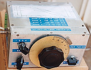
A switch selects a choice of three frequency bands. The loop
specified has an inductance of about 500 uH and using this loop the
bands are as follows:
Band 1 - 195 to 490 kHz (includes the aeronautical homer
beacons)
Band 2 - 150 to 220 kHz (includes the New Zealand
amateur band)
Band 3 - 128 to 160 kHz (includes the European amateur band).
For the following discussion on circuit detail, refer to figure 1.

|
LEGEND |
Switch S1 1. 195 t0 490 kHz 2. 150 to 220 kHz 3. 128 to 160 kHz |
The Frequency Converter
The mixer stage employs the now universally used NE602 package (N2), the output of which is fed to the input of a HF receiver. One way to operate this stage is to operate its local oscillator in a tuneable mode with the output as a fixed 1st Intermediate frequency (IF) fed to the receiver. That system, which I used in a previous converter (reference 2), necessitates the calibration of the local oscillator tuning dial in terms of the incoming LF. In this new converter, I have made use of the idea that Drew Diamond (VK3XU) used (see ref. 3). The local oscillator is crystal locked on an even multiple of Megahertz and the 1st IF varies with the incoming frequency so that the receiver is tuned over a range equal to the MHz frequency plus the LF. If the receiver is accurately calibrated, the calibration is simply read off on the receiver dial (or digital display) ignoring the MHz. In this system, the received frequency at the input of the converter is determined by the frequency tuned on the HF receiver.
For the calibration to be correct, the oscillator MHz frequency must be accurate. Drew used a frequency of 3 MHz. I had available a 3 MHz cheap ceramic crystal and a 4 Mhz quartz crystal in the HC25 holder. I started off with Drew’s circuit values but found both crystals oscillated at far too low a frequency making the receiver calibration a long way out. (This gets back to the fact that crystals are made to suit a particular circuit constants and when ordering a crystal one should always specify the circuit with the order). Anyway I settled on the 4 MHz crystal and trimmed my circuit values to make my crystal oscillate on the right frequency (refer values of C16 and C17 in figure 1). I must point out that the value of these capacitors might not be quite right for some other random crystal.
The Loop
The loop (see photo) has been successfully used in conjunction with other receiver arrangements and has been mentioned before in my previous articles on VLF/LF in AR. It consists of 20 turns of 32 x 0.2mm hook-up wire spaced laterally 10 mm apart on a wood frame 0.8 metre square. It works fine indoors and is connected to the converter via 2 metres of figure 8 flexible cable. For other receivers, coax cable was used with the cold end of the loop at earth potential. However in this receiver, the feedback signal is fed in series with the loop and the colder end of loop is at an RF potential a little above ground level. The only difficulty I have experienced indoors with the short cable is noise from the fluorescent lights. So I just turn these off. The cable can be extended so that operation is possible outdoors but the extra cable capacitance will limit the maximum tuneable frequency on band 1. There seems to be little advantage in hanging the loop more than a metre or so above ground or floor level. If kept well clear of surrounding objects it works fine.
The minimum frequency on band 1 is set by the maximum capacity of 3 gang tuning capacitor C1. The maximum frequency on band 1 is set by the loop inherent capacitance plus its feed cable capacitance. The actual minimum and maximum frequencies are of course also controlled by the inductance of the loop. The frequency range is extended downwards by switching in capacitors C2 or C3. Addition of this capacitance to lower the frequency progressively reduces the range achievable by the adjustment of C1.
With the feedback adjusted for high Q, the tuning is very sharp and a vernier drive coupled to C1 is desirable.
The Loop Interface and Feedback Circuit
The loop is interfaced by one half of twin MOSFET opamp LF353 (N1B) which operates as a voltage follower and which presents a high input impedance across the loop. A portion of N1B output is fed back into the loop across capacitor C4 via the second half of the opamp N1A. The amount of feedback or reaction is controlled by the setting of potentiometer RV1. The circuit is an adaptation of a circuit used in a previous simple VLF/LF receiver which I constructed ( ref. 4). The reason for the inclusion of R2 might not be too clear but it was added to the circuit in the earlier receiver to stop some undesirable effects caused by the rise in impedance across C4 at very low frequencies..
The output of N1B is coupled to the input of mixer N2 via drive control potentiometer RV2. This was included so that the RF drive could be reduced in the event of strong signals reaching the mixer input at sufficient level to cause cross modulation. The NE602 package has a fairly low third order intercept point which means intermodulation products can easily be produced at moderately high signal levels. (This was discussed in a previous article, reference 2). The signal levels induced into the loop are much lower than for a long antenna wire and in the practical testing out the unit, I didn’t actually notice any problem here. For my location, RV2 might well be an unnecessary inclusion but it could be needed if the converter is operated a bit closer to a local station.
Powering
The converter operates from a 12 volt DC supply which directly feeds the dual opamp N1. A 6 volt rail is derived with zener diode ZR1 and R5 and this is used for mixer N2 and to centre set the operating points of amplifiers N1A & N1B. The 12V load current is around 13mA. I operated the unit from a bench power supply but with that load current, a 12V bank of AA cells could be used.
Construction
At these low frequencies there are no real problems of lead lengths or inter-circuit coupling. Minor components (integrated circuits, resistors and capacitors) were mounted on a piece of blank experimental circuit board made for DIL packages. A aluminium box housing the components had to be large enough to accommodate the three gang tuning capacitor and the large dial of the re-cycled vernier drive I coupled to it. Almost any connector can be used for input and output. I used a twin REC socket (a twin version of the PL259) for the loop connection and a BNC connector for the 4 Mhz output. There is also nothing very critical about the design of the toroidal output transformer T1 and in fact the one I used could do with a few less turns on the secondary to suit the expected low input impedance of the usual HF receiver..
Operation and Tuning
Procedure is as follows: Connect the output of the converter to the HF receiver via a shielded line (coax cable or shielded wire). Hang the loop in a free space and connect its lead to the converter input. Connect the 12V supply and apply power.
Set the receiver tuning to 4 MHz plus the required LF frequency. Set the RF drive control to maximum. Ensure that the Reaction Control is set well below the point of input stage oscillation. (With a little practice one can recognise sounds from the receiver which indicate the oscillation point). Rotate the loop tuning control (C1) for maximum noise from the receiver. Advance the reaction control as far as possible in the stable state below the oscillation point. Carefully check that the loop tuning is set at the centre of its resonance peak. If a signal is available on the tuned frequency, the peak could be indicated by maximum reading on the receiver signal strength meter. (There are plenty of aeronautical beacon (NDB) signals available for a test). Rotate the loop antenna 360 degrees and the signal can be heard to fade in and out as it passes through the two peaks and the two nulls of the loop radiation pattern.
It should be noted that if the reaction control is advanced to the point of oscillation, the loop aerial can operate in reverse to radiate a signal at the frequency of oscillation. However this is not too much of a worry as the radiation resistance of the loop is so low that almost all of the energy generated is consumed in the loss resistance of the loop. One could expect that the signal would be of such a low level, it would hardly be detectable over the back fence.
To quote some figures, I have calculated the radiation resistance of the loop to be close to 1 micro-ohm. The RMS voltage developed across the loop in the state of oscillation has been measured as a little less than 5V. The reactance of the loop at 200 kHz is around 600 ohms so that for 5V, the current through the loop is 8.3 mA. Power radiated is this current squared times the radiation resistance which gives a power radiated of 68 micro-micro-watts, quite an insignificant figure. However, to minimise possible localised interference, one should avoid operation in the state of oscillation.
Performance
Correctly tuned up the converter separates weak signals out of the noise as good as anything I have tried out at my location. The only limitation is that is difficult to quickly scan the band with the front end so sharply tuned. It is really a o hand operation. One has to track the tuning with one hand at the converter with. the other at the HF receiver. If we know what we are looking for and know the frequency then there is no problem.
From the loop formula (ref.1) my loop is calculated to give an induced voltage of 0.05 uV per uV/metre of signal received at.200kHz. This is multiplied by the Q factor of the loop at resonance. Assuming an effective Q of 1000, the voltage at the input of amplifier N1b is 50 uV per uV/metre of signal at 200 kHz.
The conversion transfer ratio between the input of N1b at 200 kHz and the mixer output at 4.2 MHz was measured as 0.15 into a 50 ohm resistive load and 0.75 loaded into my FRG7 receiver input (obviously the antenna input impedance of the FRG7 is much higher than 50 ohms at 4 MHz).
From the above, when the loop feedback is set for a Q of 1000, the converter sensitivity at 200 kHz is 7.5 uV of converted output per signal strength of 1 uV/meter when the output is loaded into 50 ohms. Loaded into the FRG7 receiver, the figure is 37.5 uV per uV/meter.
Summary
A simple LF converter has been described which tunes the range of 128 to 490 kHz. This includes the bands allocated to European, British and New Zealand radio Amateurs and the Australian/New Zealand aeronautical non directional beacons.
The converter makes use of the noise reduction features of the small loop antenna which essential operates on the magnetic component of the received EM wave to the exclusion of the electric component which is predominant in local noise.
The loop is the only tuned element in the unit and feedback (or regeneration) is applied to the loop circuit allowing an increase in Q factor to around 1000 to 2000. This narrows the bandwidth, improving the adjacent channel rejection and reducing the susceptibility of the mixer stage to cross modulation from strong unwanted signals and high level noise.
The mixer oscillator stage is crystal locked at 4 MHz so that the host HF receiver is simply set at 4 MHz plus the LF frequency. The LF is simply read on the receiver calibration ignoring the 4 MHz.
For Noise Cancelling with Loop at LF, CLICK HERE
For Extending Active Loop to VLF, CLICK HERE
References
1. Lloyd Butler VK5BR - VLF-LF and the Loop Aerial - Amateur Radio, August 1990.
2. Lloyd Butler VK5BR - The bandwidth Limiting LF Converter Simplified - Amateur Radio, January 1994.
3. Drew Diamond VK3XU - Simple LF Converter - Amateur Radio, December 1995
4. Lloyd Butler VK5BR - A Simple Regenerative VLF-LF Receiver - Amateur Radio, January 1992.