Introduction
The original active converter as published in the July 2000 issue of Amateur Radio was made to tune the LF range of 128 to 490 kHz. Components have since been added to enable tuning down to around 12 kHz. The following text describes how this was done.
Circuit Detail
In previous loop circuits described by the writer (references 2 & 3), extension of loop tuning down to VLF was achieved by progressively switching in fixed shunt capacity across the loop using capacitance values as large as 0.47 microfarads. At the lowest frequencies, loop resonance was available at a number of spaced fixed frequencies with the shunt variable capacitor of 1350 pF having little effect . The system was workable between these spaced frequencies without fine tuning because with such a large capacitance across the 500 uH loop, the tuning response curve was very broad.
However the active loop circuit is aimed at very high values of Q which makes the tuning very sharp. Hence there is a need for fine tuning adjustment. So in this circuit, switching in of fixed shunt capacitance is limited to lower values and series inductance is added instead of large capacitance.
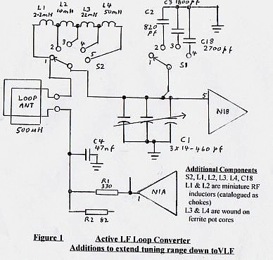
The circuit modifications are shown in figure 1. The original
circuit provided the following tuning ranges:
Switch S1 pos. 1 - 195 to 490 kHz (no fixed
capacitance)
Switch S1 pos. 2 - 150 to 220 kHz (C2 in
circuit)
Switch S1 pos. 3 - 128 to 160 kHz (C3 in
circuit)
A fourth switch position has been added to S1 which switches in C18 to provide tuning of 110 to 130 kHz without any series inductance.
A further addition is the inclusion of switch S2 which allows the progressive addition of series inductance by the selection of switch positions 2, 3, 4 & 5. By suitable selection of fixed inductance and capacity using both S2 and S1, peak tuning of the circuit using variable capacitor C1 is achieved for a continuous frequency range down to 12 kHz.
Apart from the ability to properly peak the loop circuit, the converter at VLF is far more lively loaded with inductance than with the shunt capacity. This probably results from the higher L/C ratio and the higher resultant static Q.
The inductors used are 2.2, 10, 22 & 50 mH. The 2.2 and 10 mH inductors are miniature chokes available from Dick Smith Electronics. The higher value inductors are ferrite pot cores which were retrieved from somewhere else. The 22 mH one was already wound for that inductance but the 50 mH one had to be rewound. As the characteristics of the pot core was not known, a test winding of a given number of turns was first made and the inductance measured. Given that inductance is proportional to the square of the turns, the correct number of turns for the required inductance was easily calculated form the initial number of turns and the measured inductance.
The effect of high Q
The publishing of the original article (ref. 1) has raised some discussion on the effects of running a very high loop Q. Here are some of these effects:
1. If the Q is set too high on AM or SSB the bandwidth could be too narrow and speech quality could be impaired.
2. Higher Q can be used with keyed CW than for speech because the bandwidth required is less. However there can still be an upper limit when the loop as a tuned circuit tends to ring and destroy the keying intelligibility.
3. Even a moderate value of Q might be sufficient to prevent a noise blanker circuit working in the receiver. Noiseblankers only work on impulse type noise i.e. high level pulses of short duration such as generated by spark discharge. The blanker works by closing down the receiver for the short duration of the pulse. If the pulse is fed through a high Q circuit, the short duration, high level nature of the pulse is destroyed and the blanker can’t operate. Here is a case for having a switch to connect in a series resistor with the loop to reduce Q to a very low value. For broadband noise, use the maximum Q to reduce bandwidth. For impulse noise it might be an advantage to switch in the resistor and use the blanker with wider bandwidth. .
4. The ratio of signal level to noise generated by the loop interface amplifier can be improved by raising the natural loop Q to raise signal voltage. However this ratio is not improved by the enforced higher Q due to the feedback as the amplifier noise is itself within the feedback loop. The main advantage of the feedback is the lowering of the noise power in the narrowed bandwidth created by the higher Q. It also reduces the chance of high level signal or noise outside the received signal passband from causing intermodulation in the mixer stage.
On this subject, signal level into the amplifier can also be raised by increasing the number of turns or increasing the area of the loop. However an interesting point on the loop’s own noise has been raised in an article from Break-In (ref. 4). The ratio of signal level from the loop to the noise level generated from its own loss resistance is improved by increasing area but increasing turns makes no difference to that ratio. On figures shown, the loop noise can be comparable in level to that of the incoming atmospheric noise if the loop area is too small. To ensure that the noise floor is set by atmospheric level and not the loop itself, the writers suggest that for a circular loop, its diameter should not be less than 1 metre. (The writers' comments were in specific reference to the New Zealand amateur band of 165 to 190 kHz).
Summary
The main purpose of the article has been to describe how the Active LF converter is modified to extend its tuning down into the VLF region.
Before concluding we have also digressed a little into effects of enforcing the higher operating Q and commented on one factor affecting S/N ratio in the loop itself.
References
1. An Active Loop Converter for the LF Bands - Lloyd Butler VK5BR Amateur Radio, July 2000.
2. VLF-LF and the Loop Aerial - Lloyd Butler VK5BR, Amateur Radio, August 1990.
3. Modifications to the Bandwidth Limiting Converter to include VLF, Lloyd Butler VK5BR, Amateur Radio, March 1994.
4. LF Scene - Andrew Corny ZL2BBJ & Bob Vernall ZL2CA, Break-In, July 1997.