Mobile Operations of
VK3BJM.
Back in 1997, I became interested in using 144MHz
SSB while mobile. I guess I was
interested in seeing how far you could make a mobile contact, without resorting
to the use of repeaters. Sideband has a
decided advantage over FM, when it comes to long-distance weak signal work, so
it was the mode of choice. I have heard
of stations using CW (Morse code) while mobile – but not me!
Antenna selection was the most important
consideration. Mobile antennas that are
vertically polarised may be easier to mount on a car, are less obtrusive to the
eye, and obviously work well to hilltop repeaters with vertical antennas. But,
for long distance simplex operations, the favoured polarisation is
horizontal. As all the stations whom
you may hope to work while mobile have horizontally polarised antennas, it
makes sense that the mobile antenna should be horizontally polarised, too.
My first attempt was with the V-dipole design
described in “All about VHF Amateur Radio”, by William Orr, W6SAI. It was built and mounted on my car exactly
as described in the book. It did work –
using it I managed a couple of contacts over a path of 100km, using 2.5w at my
end. But it certainly had noticeable
nulls and peaks in the radiation pattern, so I decided to try something else.
This
is the 144MHz V-Dipole.
The “Halo” was the next step. If you are like me, and have not been a
licensed amateur terribly long (since 1989 in my case), your reference library
may also be relatively new. Search as I
might, I could not find any information on the “Halo”, except a brief mention
in the RSGB VHF/UHF Handbook. I tried
building one using a Gamma-match, and had a great deal of difficulty in getting
the thing to work. In the end I gave up
on it.
However, I had noted several prominent 144MHz DXers
advising against the use of Gamma-matches on VHF Yagi, due to a tendency to
skew the pattern. They all used
balanced feed-points. So, I thought,
“Why not try a Delta match?” The first
attempt tuned up without much difficulty, as did the next four! Then came the on-air trials.
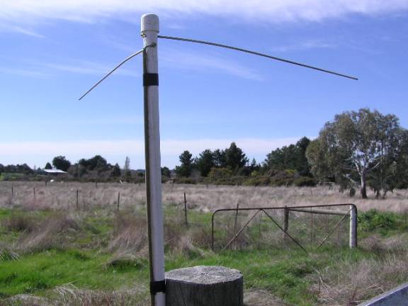
This
is the “Halo” mobile antenna for 144MHz.
Initially, I mounted the “Halo” a ¼-wavelength (500mm)
above the roof of the car. This was the
height suggested for the V-dipole in “All about VHF Amateur Radio”. And it worked – the pattern seemed more
consistent through 360°
than the V-dipole. But… I wanted more gain (or less loss?)! I decided to try stacking a pair of “Halo”. It was during comparative testing of the
single and stacked “Halo”, with Max Pickering VK3TMP and David Tanner VK3AUU,
that an easier way to make the signal “bigger” was stumbled upon. Simply mount the single “Halo” at a ½
wavelength (1000mm) above the roof, instead of the ¼ wavelength spacing! While the test was not perfect – David and I
were a bit over 100km apart, with aircraft from Melbourne Airport causing
sizable fluctuations in level at times – David was able to measure roughly a
12dB difference, between the two spacings of the single “Halo”. David used a W&G SPM-6 Level Meter,
connected into his receiver, to measure the difference. This 12dB difference is not gain,
really. The smaller spacing causes the
signal to reflect upwards, whereas the larger spacing reduces the roofs’ affect
and allows more of the signal to head towards the horizon – which is where I
want it to go.
This was good enough for me – I abandoned the plan
to stack, and used the single “Halo” at ½ wavelength above the roof for the
next three years. Many memorable
contacts were made during that time. I
also made other improvements to the mobile station, with the addition of a
low-noise pre-amp, an increase in transmitter power to 160w, and the
replacement of the RG-58 feeder cable with RG-213.
I wrote up a construction article for the design, and this was published in the
now defunct “Radio & Communications” magazine in October 1998. The link below will download a PDF of the
article:
The following log contains some of the more
memorable contacts that were made during this period.
|
Date |
Time (z) |
Name / Call |
RS |
RS Rx |
Distance |
Propagation Mode |
|
22/2/98 |
2220 |
Roger, VK5NY |
53-59 |
53-59 |
650km |
Tropo |
|
3/10/99 |
0438 |
Gordon, VK2ZAB |
41 |
51 |
|
Aircraft Enhancement |
|
27/3/00 |
0926 |
Glenn, VK4TZL |
51 |
51 |
964km |
Meteor Scatter |
|
|
|
|
|
|
|
|
|
|
|
|
|
|
|
|
Of course, this small taste
increased my appetite to do better. A
“Halo” is simply a dipole bent to form a circle. It radiates some signal in most directions. But in any one direction, the most you can
see of the antenna is 50% of the dipole – half of the circle. This is obviously has less effective
“capture area” than a dipole that is in its normal form. To do better, I had to increase the capture
area, and to do this meant applying the old rule: “Bigger is better”.
This could be done in one of
two ways: stacking multiple halos, or trying another design. I didn’t want to revisit the stacked pair
due to the height problems this involved.
In 2000 I went back to the books to find another design, and started
asking around. Both John Martin VK3KWA
and David Tanner VK3AUU had mentioned a design called the “Big Wheel” (also
known as the “Cloverleaf”). John had
made one, which I’d seen, but he’d not felt that it was working correctly. However he emailed me some JPEG files of the
info he had, which included an American design for 144MHz and a German design
for 432MHz. Whilst I was temporarily
working in Sydney in 2000, I built the 432MHz version, and found it worked
well. Initial tests included taking it
for a drive down to Canberra, and working Gordon MacDonald VK2ZAB in Sydney
from there.

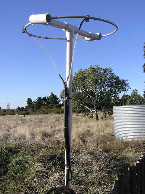
The
“Big Wheel” antenna, for 432MHz, showing the cable gland mast-mounting
arrangement.
On my return to Melbourne in
November 2000, I started work on the 144MHz model. While I’d made the 432MHz model from 3.175mm copper rod, I wanted
to make the 144MHz version from 6.35mm aluminium tubing – stronger and lighter. This differed from the ARRL design, which
used 10mm tubing. I also had my own
ideas about the clamping arrangement for fitting the antenna to the small
mast. My initial attempt had the
element length as described in the design drawing, but it was resonant at
136MHz – 8MHz down from where I wanted it.
Interestingly, John Martin VK3KWA told me later that his had also tuned
up at a similar frequency. I chopped
25mm from each end of the elements – and the resonant frequency came up to
140MHz. Off came another 25mm, and
there we were on 144MHz.
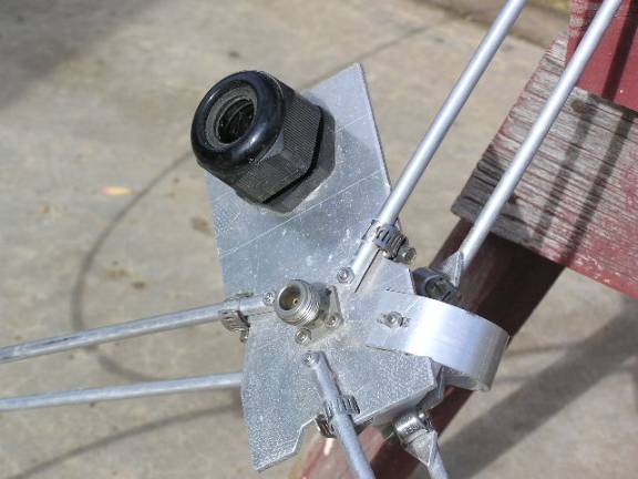
Detail of the element
mounting arrangement for my 144MHz “Big Wheel” “omnidirectional” horizontally
polarised mobile antenna (struth, what a mouthful…).
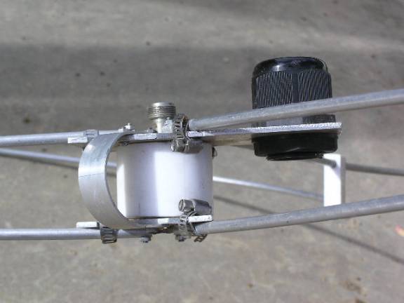
Cross section showing the top and bottom plates,
the Teflon spacer, and the M32 cable gland that clamps the “Big Wheel” to the
supporting mast.
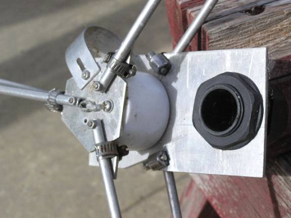
A view of the top
plate.

A view of the
complete “Big Wheel”.
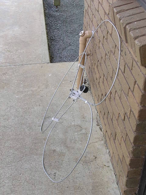
And one more for
luck…
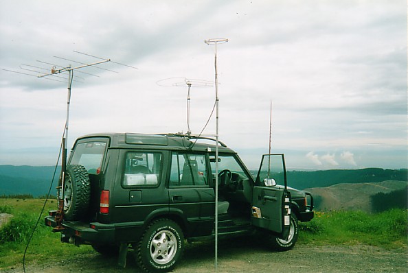
Comparing
the “Halo” with the “Big Wheel” at the lookout on Mt Tassie, VIC; December
2001.
It’s easy to see why the “Big Wheel” does better than
the “Halo”. Its circumference is 1.5
wavelengths (about 3m), three times greater than the “Halo”, which has a
circumference of 1m. It consists of
three dipoles, each of which is distorted less from their original form than
the single dipole “Halo”.
And from my experience the Big Wheel certainly
out-performs the Halo. I’ve been using
the Big Wheel exclusively since 2001, with several major trips from Victoria to
South Australia, up the Hume Highway several times to Sydney, up the Newell
Highway to Queensland, and numerous trips around Victoria and into the far west
of New South Wales. The majority of
contacts occur via Aircraft Enhancement, with two Meteor Scatter contacts
during the 2002 Leonids Meteor Shower to keep things interesting. Based on the many AEP contacts I’ve had with
stations in Sydney while travelling on the Hume Highway, my rough estimate is
that the Big Wheel has 100km greater range than the Halo for that propagation
mode.
It’s hard to see how to do much better in the mobile,
horizontally polarised, omnidirectional stakes than the “Big Wheel”, if you
wish to limit yourself to a single antenna.
I have no wish to attempt mobile operation with a pair stacked with even
a one-metre spacing! Not least of the
considerations in going even bigger is how to make it strong enough to survive
a constant wind speed of up to 110km/h.
And no one needs the attention of Mr Plod focussed on them needlessly…
Last update:
3/2/2011