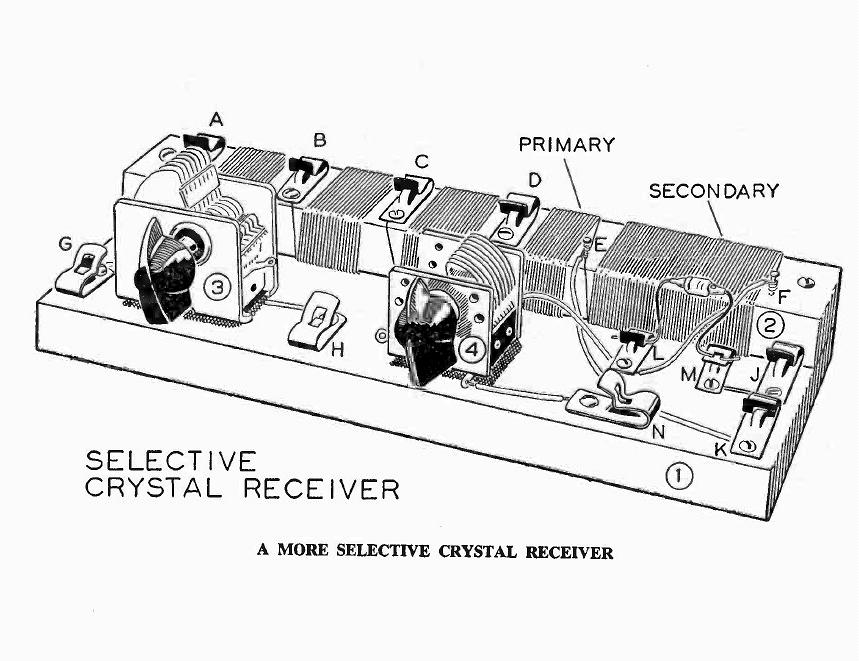
"A More Selective Crystal Receiver"
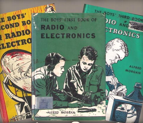
If you're anything like me, hooked on the magic of radio during my pre-teen years in the late 50s, then you're no doubt familiar with Alfred P. Morgan's great series of radio books for boys. I still remember the cozy library on the top floor of my elementary school having copies of both The Boy's First Book of Radio and Electronics' (1954) and The Boy's Second Book of Radio and Electronics' (1957). As much as I had hoped to find another radio-crazed kid in my school, the book's pocket sign-out cards had just my signature only, at least a dozen times! Incidently, Alfred Morgan's career was much more than just writing great books as this quick biography describes his very busy life involving radio and electronics.
Back then, I had found 'A More Selective Crystal Receiver' in Morgan's second book to be intriguing but at my young age did not have any idea where to obtain the needed parts and had not developed the skills needed to actually build it.
More recently, I have been seeking out circuits for simple basic crystal radios, suitable for beginners but also ones that might offer the possibility of hearing DX (skywave) signals as well. I had no high-performance expectations when choosing Morgan's circuit. It's orderly physical appearance, more than anything, garnered my interest ... so some 60 years later, it was now or never!
The design paid little attention to circuit losses, using inexpensive variables along with a low-Q coil wound on a lossy wood form. What did give me a tiny glimmer of hope was that the variable capacitors appeared to be identical to those used in Heathkit's legendary CR-1 Crystal Radio, a superb performer, introduced around the same time as Morgan's book!
Once I had decided to build Morgan's circuit, I had a much closer look at what was in store. I had just purchased the two inexpensive variables capacitors and already had the needed #24 enameled wire along with the necessary Fahnestock clips.
Morgan's design, shown here, was intended to be sufficiently versatile so that young builders could experiment with various circuit configurations. One of the two variables (4) was devoted to tuning the detector tank coil while the second one (3) was left unconnected altogether. It's purpose was left up to the builder. What a brilliantly unique concept on Morgan's part to encourage learning when most other published circuits called for the lock-step duplication of the author's circuit!
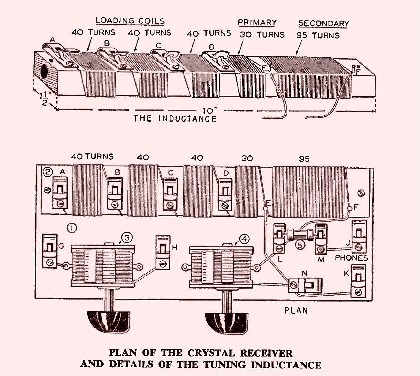
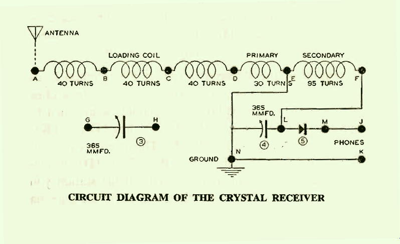
Studying the design more carefully, it appeared that the first four separated windings were to be used for the antenna loading circuit while he called the shorter fourth section the "primary" winding and was to be used to couple the antenna into the larger detector winding or "secondary". In reality, this was all one long single coil, with four taps, with the bottom end permanently grounded!
My first thought was that Morgan had under-estimated the needed inductance to fully tune the antenna circuit as well as the detector circuit from one end of the broadcast band to the other. I was able to locate an online inductance calculator for rectangularly-wound coils in order to learn more.My suspicions were confirmed when the inductance of Morgan's coils were calculated using the online calculator. Using his specified capacitance of 365pfd there was no problem reaching the top of the band, but the lowest it would tune was around 660kHz. Most antenna tuning circuits like around 350uH to effectively tune most antenna systems but this one provided only 160uH.
Similarly, the detector coil worked out to be only 135uH, not the 250uH usually seen for this inductor. Using his 365pfd capacitor would only allow tuning down to 700kHz. Perhaps Morgan intended to stretch out the high end so that young builders could listen to neighbourhood radio amateurs on 160 or 75m phone, who in those days would have been on the AM mode and readily detected.
Just to confirm the accuracy of the calculations, a 40-turn test coil was wound on a form of the specified size (1-1/2 x 3/4) and measured to be 40uH, very close to the calculated value.
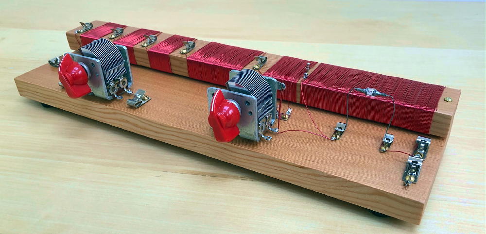
I decided to modify Morgan's circuit by increasing the inductance of both coils to ensure that tuning would reach the bottom of the AM band. As well, the permanent ground connection between the "secondary" and the "primary" coils would be eliminated to provide even more versatilty with respect to the coils and the tuning arrangement.These changes required a lengthier coil form and matching breadboard, slightly changing the overall profile and appearance of Morgan's plan but still maintained the simplistic look that attracted my attention decades ago. With theses changes in mind, and as I usually like to do before starting construction on a project, a full-size drawing of the finished design was made.
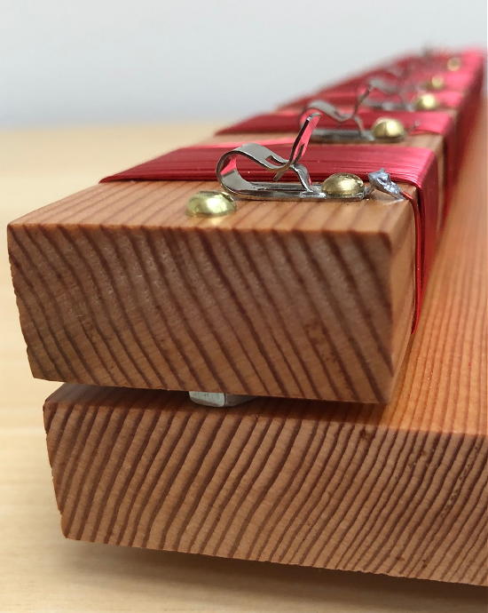
The wood for the coil form and the base were cut to size using B.C. Douglas Fir. Both pieces were given four coats of polyurethane spray varnish. The capacitors were insulated from the base using nylon screws and nuts in an effort to reduce any signal loss by putting them in direct contact with the wood. Insulating them in a low-Q system such as this would likely never be noticed ... but I have been able to actually measure the signal loss on a higher-Q system when the capacitors are moved onto the wood base ... so every bit of help, even if tiny, contributes overall.
Similarly, the coil form block was also insulated from the main wooden base in an effort to keep the bottom of the coil from touching the wooden base ... touching the form itself is lossy enough. Whether either of these measures resulted in any improvement will never be known, but for certain it can never make the situation worse! Two of the detector circuit wires were run along the bottom side for de-cluttering purposes.
As each winding progressed, varnish from the copper wire was scraped away before tinning with solder and wrapping it tightly around the brass Fahnestock screw then continuing to the next coil. Winding and securing these coils correctly might be pretty challenging for a young builder as it was challenging enough for myself!
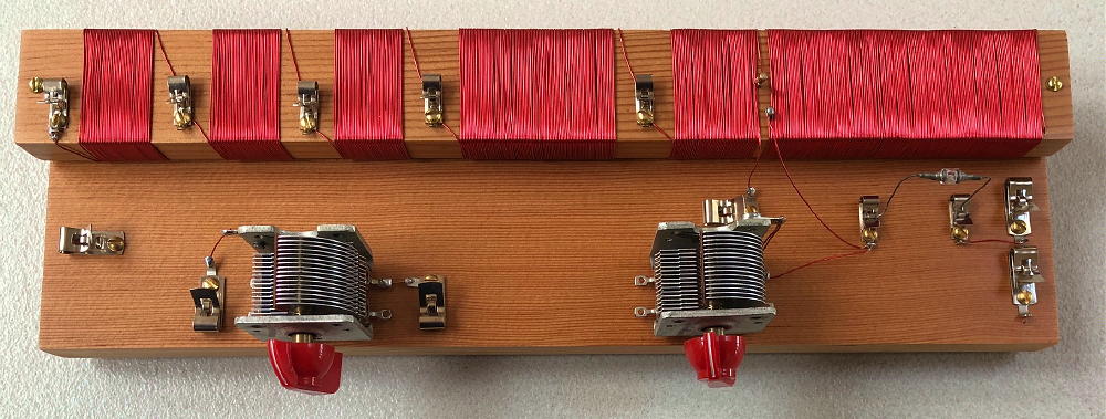
Overall I was very pleased with the look of the finished receiver as the new dimensional changes did not affect the overall personality of Morgan's design. Although we will never know, I'm hoping that Morgan also chose red knobs for his receiver!
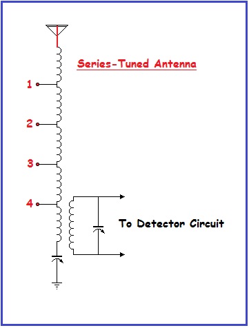
So how would Morgan's 'More Selective Receiver' perform? As previously mentioned, I had low expectations in view of the lossy, low-Q character of so many of the circuit elements. In addition, my location is a nightmare for crystal radio reception as there are presently 15 individual (10-50kW) stations within 25 miles of my antenna. All of these stations qualify for 'blowtorch' status as 12 of them produce between 100 and 450uA of crystal current on my main Crystal DX receiver. Would it even begin to separate the locals or would it be one big glob of mixed signals?I chose to configure the unused variable capacitor in a series-fed antenna tuner, exactly as done in the Heathkit CR-1. I've found that this particular arrangement seems to work well with my inverted-L antenna. I have yet to experiment with parallel tuning as so many others seem to favor. Each antenna is different and what works for some may not work for everyone.
Being able to tap the antenna down at the various points along the antenna coil made a huge difference in being able to separate signals. On more than one occasion, an interfering local signal completely vanished simply by moving the tap up or down and re-tuning the capacitor.RESULTS
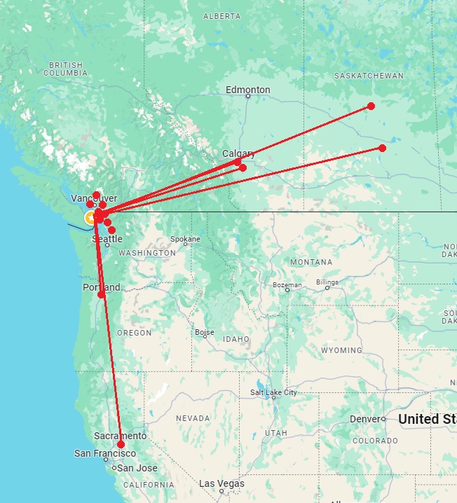
The receiver performed very much beyond expectation! During the day I was able to easily hear and separate all of the 15 flame-throwing local stations thanks to the series-tuned antenna stage. As nightime approached I added a simple outboard tuneable wavetrap in the antenna lead which allowed me to deeply null out some of the worst offenders as I tuned across the band. I was very surprised to easily hear stations in Alberta, Saskatchewan, Oregon and California thanks to the outboard trap. I was particularly delighted to be able to log CBK (Watrous, SK on 540) right next to blowtorch KARI (Blaine, WA) just 25 miles away.
I have no doubt that this configuration of Morgan's receiver would make an inexpensive worthwhile beginners project. If the builder lived in an area with few strong local signals, it would be easily capable of hearing DX signals with a decent antenna and ground. I will spend further time playing with it and any further developments will be posted to Facebook's "Crystal Radio DX" Group.
CRYSTAL RADIO LINKS
THE LYONODYNE - A detailed description of Mike Tugggle's DX Contest winning set. Probably one of the most efficient DX sets ever built!
A CRYSTAL DX SYSTEM -A superb description with all building details...a must see!
STAY TUNED - Everything you need to know about sound-powered phones is here. Hundreds of crystal radio building plans, schematics and suppliers. A superb site!
FACEBOOK Crystal Set Radio Group - A very active group of over 5,000 members with all ranges of experience!
FACEBOOK Crystal Radio DX Contest Group - A new group to discuss the next DX Contest!
CRYSTAL RADIO SET SYSTEMS - Design, measurement and improvements. Detailed circuit analysis by a brilliant engineer, Ben Tongue.
SCOTT's CRYSTAL RADIOS - Huge selection of headphones, including Sound-Powered phones for sale!".
KEN HARTHUN's SW SET - Build a Short-Wave version of the 'Mystery Set'
KEN HARTHUN's SW SET EXPERIMENTS - 'Mystery Set' improvements.
CRYSTAL-RADIO - Dick Kleijer's first class site. Excellent info on re-building capacitors for higher - Q as well as detailed measurements of L-C "Q - killers".