Experimental Short-wave "Mystery"
Crystal Radio
by Ken Harthun
Copyright January 2001
This is not the typical crystal set construction article to which you may be accustomed; rather, it is a description of a few workable circuits that leaves plenty of room for experimentation if you are so inclined. You can build a fine working short-wave crystal set based on what I give you here. These circuits perform very well. However, I’m still experimenting with them and I challenge you to do the same, to discover what works best for you. Tinkering with a circuit, trying different things to see what works – and what doesn’t – is the essence of our hobby and is what keeps this particular rock head interested!
Because this set is experimental, I make no claims that this design – or any particular hookup that results from this article - is the ne plus ultra in short-wave crystal radios. We all know that the perfect crystal set does not exist. The "perfect" crystal set for my location is something that may or may not work for you (I have to deal with a 50Kw blowtorch that is located virtually in my backyard – you may be more fortunate).
My antenna is about 150 feet of wire in an inverted V with the apex at about 35 feet. Some of it runs every-which-way across my roof and into my radio room. Though at BCB frequencies my antenna is much too short, it is actually much too long an antenna at short-wave frequencies. You can probably get by with a lot less, depending on your location.
With these things in mind, let’s begin and take a look at a project that I believe will give you plenty of enjoyment – and will probably raise many questions. In fact, I hope that this article will generate enough interest in short-wave crystal set reception that we see some real innovation in future designs.
The radio is based on the Mystery Crystal Set designed by a fellow who called himself "Proton" and who first published details of the set in the Sunday Mail newspaper in Brisbane, Australia in 1932. I won’t rehash any of the details because the set is well covered in the articles posted at http://www.clarion.org.au/crystalset/mystery.html by Ray Creighton. I have simply adapted the circuit and modified it a bit for my set. Fig. 1 is the basic schematic.
Construction
The coil form is a 2.5 inch long piece of 2" white PVC plumbing pipe with an outside diameter of 2 3/8 inches. This is the kind that has a thickness of about 3/16 inches and is known as "Schedule 40". Construction details are shown in Figure 2.
L1 – 20 turns #22 close wound, approx. 35 uH
L2 – 13 turns #18 or #20 wound at 20 tpi, approx. 12 uH
L3 – 6 turns #22 bifilar wound in the center of L2
C1 – I’ve been using a 20 – 56 pF air variable for coverage of approx. 6 – 10 MHz and a 13 – 250 pF air variable for approx. 2.9 – 12.7 MHz coverage with the coils shown.
Diode – 1N34A or crystal detector.
(You may find as I did that a piece of pyrite and a cats whisker work much better than a diode. For some reason, I find that the pyrite detector is more sensitive and gives me much better volume than the diode. Also, with pyrite, you can eliminate the resistor across the crystal earplug.)
Resistor – 47K (*Note: you can eliminate this resistor if you are using high impedance magnetic headphones)
Phones – crystal earplug or high impedance magnetic phones
I have been using alligator leads to connect it up so I can rapidly change configurations. The photo shown at the beginning of this article is a completed homebrew version of the set that uses mostly non-electronic parts (except for one Fahnestock clip hat was used to hold the detector rod). The capacitor is made from a plastic tube and some aluminum tape that you can find at auto parts stores.
In the original coil I wound, I used hot-melt glue to hold the windings in place. About six beads or "ribs" across each of the windings works very well. Also looks pretty good – better than tape!
In the basic "mystery" circuit shown in Fig. 1, L1 is not used. The tuned primary (L2) has two antenna connection points, A and B. A is the least selective, but gives a louder signal. B is more selective, but the sensitivity drops notably. While I show a ground connection, I noticed that results vary. In most cases, I find that the set works better in this configuration without a ground and is very sensitive. Selectivity is enhanced with the ground connected, but some signals drop out while others get louder. I’m not sure why this is and I’m still experimenting. I have tried putting a small trimmer capacitor in the ground connection to vary the coupling to ground, but my results are inconclusive at this point.
Overall, the basic configuration works very well and is a fine set in its own right. I easily pick up WWCR at 5070 kHz, WEWM on 9975 kHz, have heard Radio Havana (Cuba), the BBC and many other German, Chinese, French and Spanish language broadcasts. My first night, I picked up a station that was running a program called "Let’s Learn Chinese". Bear in mind that propagation conditions vary considerably. You may or may not hear this much at first. Then again, you may hear even more. Some evenings I hear very little but I’m listening as I work on this article in late February and there seems to be stations everywhere as I tune. The audible stations fade in and out and back again, so I get a good variety without having to touch the tuning dial!
As I mentioned earlier, in my location near Cincinnati, Ohio, I have a 50 kW blowtorch, WSAI on 1530 kHz, virtually in my backyard. I have to use a wave trap to tune this station out or it’s all I hear. As a matter of fact, I can hook a diode up to a crystal earplug, hold the diode in my hand and still hear this station loudly! My point is that your conditions will certainly be different than mine, so there is no way I can tell you what to expect to hear. But I can almost guarantee that you will hear something.
Figure 3 shows another configuration I have tried.
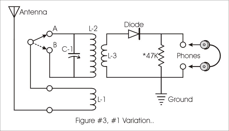
In this configuration, L1 is used as a coupling coil for the antenna and one end is attached to either A or B on the primary. This is a very interesting hookup, more selective than the basic circuit in Fig. 1, but not quite as sensitive. With L1 hooked up to point A, the selectivity is quite sharp. When hooked to point B, the set is so selective that tuning can be tedious. Again, the ground is optional, but I find a little better sensitivity in this hookup with the ground connected and the selectivity hardly suffers at all. One thing to try would be to decrease the spacing between L1 and L2/L3. I think that the current spacing may result in coupling that is a bit too loose for this set.
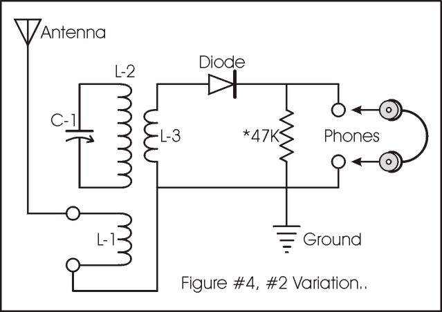
The configuration detailed in Figure 4 shows some promise for daytime reception in the upper short-wave bands and for further development as a set with variable coupling. With the existing design, the coupling between L1 and L2/L3 is somewhat loose at the ½ inch spacing. Making L1 moveable and possibly large enough to fit over L2/L3 are some things I am considering.
Here are some ideas for further experimentation.
This is by no means a complete list of the things that can be tried with this circuit. In fact, I even redesigned the coil to the following dimensions:
L2 – 18 turns #20 space wound to 1.3" long, 2.375" diameter for approx. 20 uH.
L3 – 7 turns 7/30* bunched cable bifilar wound in center of L2
L1 is not present in this configuration.
*7/30 cable is 7 strands #30 enameled wire twisted into a cable of approx. size of #20. Individual wires are stripped at the ends then twisted together and tinned.
I hope I have given you some food for thought and inspired you to try your hand at making this interesting circuit work. I intend to continue my own experiments and perhaps write another article at some future time. If you want to contact me, you can post a message on Rap-n-Tap, the Yahoo Crystal Set Radio Club, or email me at [email protected]. I welcome all comments and suggestions.
Good luck and Happy Experimenting!
3/18/2001 Notes on further modifications
L1 is now present again on the redesigned coil. It comprises 8 turns of # 22 AWG close wound, spaced ¼" from the bottom end of L2. The antenna and ground connections are made to this coil.
L2 is now 14 turns instead of 18 turns to bring the coil more in range of the most active SW bands.
L3 is unchanged.
Experiments with a Perikon detector are very interesting. My Perikon detector consists of a piece of chalcopyrite in contact with a small cone-shaped piece of zincite. It is equally as sensitive as my pyrite detector – maybe more so under some conditions – and has an interesting property in that it appears to be somewhat "tunable". I’m not sure if this is due to signal strength or has more to do with the frequency to which the set is tuned, but I observe a distinct ability to peak signals differently as I tune across the bands. I seem to recall some mention of this property in early radio literature.
One big advantage of the Perikon is that it is not as touchy as the typical catswhisker-and-mineral detector. It is easy to begin detecting a signal and once detection begins, it is a simple matter to peak the signal. I also observe that the Perikon requires a bit of pressure to work properly. It doesn’t require the light touch like other point contact detectors and adjustment is non-critical. Unlike the catswhisker detector, the Perikon doesn’t mind being bumped and tends to keep its setting. It is very stable. I like this detector a lot.
I tried a zincite/pyrite combination, but you can forget that one. Just doesn’t work. Likewise, chalcopyrite with a catswhisker just isn’t very sensitive. It works, but it seems to been just a couple of steps up from a rusty razor blade. Yes, the razor blade detector actually works on this set on some of the stronger signals. And I have to say again that a 1N34 germanium diode just lacks sensitivity in this set. It doesn’t work as well as either the Perikon or the pyrite detectors.