|
|
|
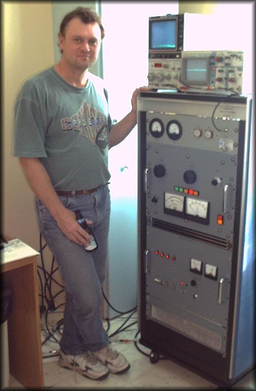
Technical Description of the HF amps built for VE5RI contest station by VE5FF: The MK-1 and MK-3 (Cyclops) Check out the
Schematics
Page!
More Pictures of AMPs The New 2 Holer! Casualties of Contesting!
MK-1: Operating
Parameters: Ep: +3kv-dc Ip: 900 ma Ec1: -60 vdc Ec2: +325
vdc Idle current
for AB1 operation: 300ma Plate
dissipation: 1500 watts
Circuit Description,RF deck: The tube is
used as a single ended linear amplifier with the screen grid connected directly to the
chassis. All supply voltages are referenced to the cathode. This means that the chassis
becomes the RF ground reference, with the DC return path “floating”. RF drive is supplied to the control grid across a
50ohm non-inductive resistor and through a coupling capacitor. The benefit of this
configuration is twofold; when the screen grid is operated at RF ground the input gains
the greatest isolation from the output. Neutralization is not necessary. Input circuitry
is also simplified, there is no requirement for a switched matching network for the
control grid. The capacitive reactance (about 80 pf) presented by the tube to the exciter
at 28 mhz may be cancelled with an inductive reactance shunted across the 50 ohm
terminator when operating on 12/10 meters. This
scheme was not incorporated in this particular amplifier because the exciter used is a
TS940 with auto-tuner. The output
uses a conventional Pi-network with 10kv vacuum caps for tune/load and a roller
inductor/tapped inductor scheme. The roller is used to tune 160-40m, the tapped coil for
20-10m. You may have noticed that the tube is mounted in the horizontal plane. One unique
feature of this tube family is that it can be used in any mounting position, while the The high
voltage is fed to the plate via two RF chokes of different values and design (120uh/60uh)
placed at right angles to each other. This avoids crazy choke resonances in the amateur
bands. Power Supply and Control: The HV power
supply uses a pair of oil-filled transformers rated at 110/220 v input/2200 v secondary @
1 amp. A full wave bridge with 8 electrolytic capacitors (450uf/450v) make up the rest of
the supply. Voltage output no load is 3000v. Nothing exotic about the design, strictly
radio handbook modeling here. The screen
supply consists of a 400v center tapped transformer with a variable transformer on the
primary. A full wave bridge is used with capacitor input and a string of HV zener (50
watt) diodes shunt fed. RF bypassing is a must, I discovered that zeners don’t like
stray RF! This supply will be changed to active shunt regulator ( HV mosfet). The Control
Grid bias supply uses a 90volt transformer with full wave bridge. Output is -20 to-100
vdc. This allows you to adjust the bias for Class C to operate FSK and CW. Because the amp is run in AB-1 for SSB, this
supply doesn’t have to be rated for high current by virtue of the fact that no grid
current is drawn in this mode. The 4CX1500B is rated for AB2 operation, but typically not
operated there. Note that the 4CX1000 should not be operated in AB2. Filament
voltage is 6vac/9amps.The cathode is indirectly heated. One downside in using the 1000A
or1500B is that the cathode requires warm up of about 4 minutes before you can operate. If
you insist on ignoring this fact, you will end up destroying the tube prematurely (shorted
grid to cathode). The control
loop monitors screen current (sometimes
negative) in order to protect the tube from an overload condition. An overload can be caused by You may ask
why use a tetrode when a triode seems to be less complex to use. There were a few
considerations that helped me form a design philosophy. The prime
goal was to use a device that offered exceptional operating characteristics in linear
amplifier service with a minimum of drive power from the exciter and be able to deliver 15
db of gain. The operating voltages had to be “low” in order to keep the cost of
the power supply within reason. The tube had to be readily available from the surplus
market as a “pull” (replacement cost control). So performance and economy became
the design criteria. Of course there is added complexity with the addition of bias, screen
and control supply/circuitry, but the time spent in designing and building these was not
significant. Another FAQ
is why not use tubes from this family in triode grounded grid configuration. There is one
good reason for this; because the 4CX1000A and 4CX1500B were specifically designed for
linear amplifier (AB1) service this
requirement influenced the design of the grid structures (low electron intercept).The
control grid dissipation of the 1500B is
rated at 1 watt and the screen is rated at 12 watts. When you connect the grids together
and then operate in grounded grid the control grid will draw almost 75% of the total grid
current ( do you remember how much grid current is drawn by a pair of 3-500’s?). You
WILL destroy the tube in this mode. The 4-400 and 4-1000 can be used as triodes (screen
and control grids strapped together) in AB2. Because they were originally designed for
class C operation, their grid structures use a different design scheme and the dissipation
ratings are greater. As well, in order to get any power out of these tubes, you should be
operating the plate at 4kv with 100 watts of cathode drive.
The design
of this amp incorporates the Eimac 4CX3000A /8169 power tetrode. This tube is designed
specifically for linear amplifier service. Essentially the same circuit design is used as
the MK-1, with certain exceptions. The control grid input requires a 1:4 un/un transformer
terminated with a 200ohm resistor. This is used in order to get RF voltage step-up. RF input voltage has to overcome the dc bias
voltage (-160 volts) in order to drive the control grid. The Screen power supply uses an
active shunt fed regulator (HV mosfet
controlled with an op-amp used as a voltage comparator, courtesy G3SEK). Normally the
screen potential is 300 volts . This amp was designed for 100% duty cycle-FSK/CW/SSB
modes. There are
some differences between the 4CX1500B and the 4CX3000A. Mounting is vertical only and the
filament is instant on. The filament material in the 4CX3000A is thoriated tungsten while
the cathode in the 4CX1500B is oxide coated. One interesting point to consider is that
large power tubes using thoriated tungsten filaments can be rebuilt for about 60% of new
cost. 4CX3000A
operating parameters: Ep 5800 vdc Ip 800 mA Ec1-160 vdc (adjustable to -300). Ec2 300 vdc Filament: 9
v @ 40 A Idle current
in AB-1: 500 mA Plate
dissipation: 3500 watts Control Grid
Dissipation: 50 Watts Screen Grid
Dissipation: 175 Watts IMD: -35/-42
db RF power out with 50 watts drive: 2000 watts.
Gerard Hnatiw VE5FF
|