Last
updated Dec 2003.
Special thanks to Mr.John
Van der Ryd (VE3CYC) for
the original idea
Click on
pictures to get the magnified view
After moving into my new house, I started
the rebuilt of my antenna farm. On considering the quickly approaching winter
plus potential comments from neighbors, I finally decided to limit the
construction within the attic. I need a low profile but highly efficient
system. My antenna inventory list includes:
- UHF high gain antenna for VA3CTR repeater.
- UHF/VHF dual band for local contact
- 6m vertical ground plane antenna.
- H.F. beam antenna for 20m and 15m.
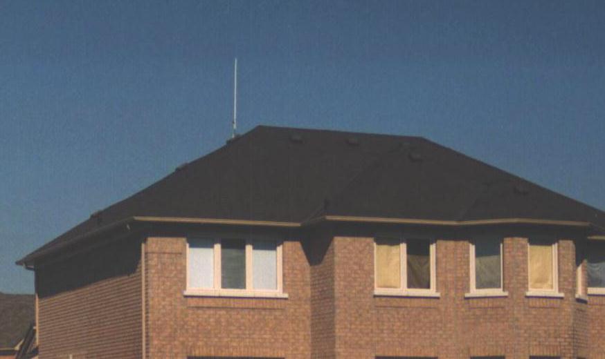
This roof
housed all the above mentioned antennas !
Design selection
The interior of an attic is made mostly of
wooden frame. They are perfect for mounting antenna poles or pinning down wire
elements. Since the attic is inside the roof, it is protected from outside
environment. Antenna installation in this area needs very little water
proofing. The only trade off is the extra attenuation after water or wet snow
has coated the shingles of the roof. That might make application of precise
tuning antenna designs unstable.
I already have two factory-built UHF/VHF
antennas. In order to compare the lost caused by the attic, I installed both of
them (Diamond X50 and its clone) inside and outside the roof for performance
comparison. Based on the same design and length of cable run, the difference in
performance is a combined factor of R.F. shielding and a slightly lower
elevation of 10 ft. The result turned out to be a weaker performance for the
antenna placed inside the attic. The difference between the two is
approximately 6db. It is quite an amount of power lost but that's the cost of
employing in-building hidden construction.

The
outdoor X50 dual band antenna
My 6m-ground plane
is another cheap built. I just soldered a piece of insulated wire (50"
long) to the core of a SO-239 socket. Three insulated wires of the same length
are then secured onto the mounting holes of this socket and stretched out to
maximum length to form the ground plane. The length of the core conductor is
then gradually trimmed in 1" intervals until the best return lost (S.W.R.)
is obtained on the lowest portion of the band. The wires are just nailed onto
nearest wood frame for holding. The appearance is ugly (that's why no picture)
but it works fine.
The H.F. antenna is the biggest issue. I'd
once seen an article in 73 magazine (by VE3CYC) which
described the building of a wire beam antenna. I had been using part of that
design (the single element dipole version) during the past 2 years at my old
house and had obtained an amazingly good result. With the size of my new attic
(35'x40' roof area with a 10'x25' patch cleared for standing up), it is fully
possible to have the whole wire beam housed. The neat part is that I don't even
need poles, insulators or cords to hold up the wires. All wire elements can be
stapled on the plywood roof or any near by 4x 6 wood logs.
The wire beam design
The beam composed of two dual-band dipoles
(20m and 15m) placed 10 ft. apart. Only one of the two arrays is being used at
one time. With the other side hanging in mid air, the vacant dipole forms a
parasitic element. The array is basically a YAGI composed of 2 elements. For
such design, the parasitic elements are shorted and should be built longer (as
reflector) then the driving element. In this wire-beam, unlike a conventional YAGI,
both elements have chances to serve as a driving element. This forced them to
be built with the exact same dimension. The parasitic nature has to be achieved
by loading of external elements. By switching between array-A and array-B with
the unused side loaded with a non-terminated feed line, a directional effect
will appear. Signal will usually be stronger on the direction where the active
array is in front of the parasitic array.

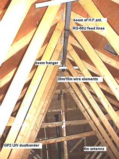
Circuit diagram of the wire beam antenna.

3D figure
of the wire beam secured inside the attic.
The wood frame of the roof section is not
shown above to prevent confusion. The boom of the beam is a PVC pipe (3"
diameter and 10 ft. in length). Two RG-58U cables are routed to both opening of
the boom from the center portion. R.F. chokes are required to prevent R.F. pick
up to travel back down the origin and causing unexpected interference. They are
made from 8 turns of tightly coiled up feed line of each individual dipole on
the boom. The end of each cable is then spliced. The exposed core and braid are
then secured onto two screws that are used to hook up those 20m and 15m wire
elements in future.
To make it simple, starting length of 20m
wire elements are 190 in. while that for 15m are 130 in. The length of all wire
elements listed above are just reference. Final length
will alter with different attic environment anyway. Length of each wire will
have to be trimmed individually. As long as wires on the same plane are cleared
from each other by distance or at a separating angle, they won't interfere with
each other. In order to get the most accurate result, wires of the first dipole
has to be detached temporary from the boom when dealing with tune up of the
second dipole. For my case, I had to cut off nearly 24 in. of wire for the 20m
and about 14 in. for 15m before I can bring both dipoles into proper resonance.
The final wire length for 20m elements are 156 in./168
in.(dipole one/dipole two). The final wire length for 15m are 108 in./114 in.)
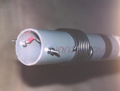
Head-piece of the boom
Working inside the attic
Working inside the attic did border me at
the beginning. The floor of the attic is basically a wood frame with the
ceiling boards hanging from its bottom. One can only walk on the wood frame. If
you step on the dry wall, you can easily punch a hole and drop straight
through. It is not funny if you made a landing on top of the open concept area
and stop at the basement. What makes it worse is that the whole attic floor is
sprayed with insulating material. You can imagine yourself walking in a pink
snow 12" deep. The wood frame is invisible until the pink stuffs are
cleared off temporary. Even with good illumination, it will be very distracting
if you have to watch you steps when you are trying to work on the antenna. I
got an advice from VE3HVL. It turned out to be a very good practice. I got some
cheap 0.4" chip-wood boards (48"x96") and cut them up into 16"
strips. The strips must be narrow enough to pass the manhole (access of the
attic) but still wide enough for you to walk on. Once these strips are moved
into the attic, place them on top of the wood frame and make yourself a
catwalk. Moving around will then be much safer although
you still have to watch for those overhead frames. It is also important to
carry a dry battery torch even though you have installed temporary
illumination. That prevents you from running into unexpected total darkness.
For example, when the bulb is toasted or when your XYL unplugs your attic light
by accident. If you have an aged house where the attic is dusty, always wear
mask and air filters. Inhaling of these dust is not
healthy.
Running the feed lines
In order to make the whole package neat
(so that the XYL can't complain on degrading the house value), I run all R.F.
cables inside the drywall. The walls of our house are all gypsum boards mounted
on 6" wood frame. If the wall is not back to the exterior wall, it doesn't
need insulating material. That hollow area is perfect for cable routing. I
chose the wall behind my station's desk and punch a 2" hole on it. A desk light is then switched on and have the back side of
the hole shined up. The distance of this hole from the nearest corner is then
measured. Once back in the attic, a hole is drilled on the wood frame on top of
this spot (using the distance from the corner as reference). A perfect line up
is verified if the lighted spot of the inside wall can be seen. Drill another
hole if the line up is not straight down. Once the holes are made, cables from
the attic area can be lowered and retrieved from the 2" hole on the
bottom. The bottom hole can then be closed up with a cover plate in future
after all cable work is completed.
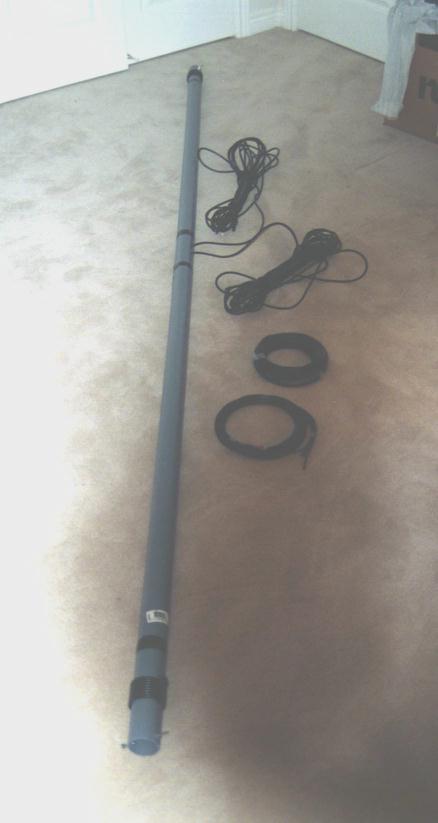
Constructing the antenna
The material for the wire beam is cheap. I
spent only $50 for the boom, wire and 150ft of coaxial cable in total. The
first step is to secure the boom on the highest point of the attic. Feed lines
are then dropped down and brought up to the antenna switch at the console.
Construct one side of the beam first. All elements of the antenna need
clearance from each other. Elements hooked on the same connecting screws have
to be placed 30 degree apart. Main parts of this antenna can be seen below.
Do not attempt to tune up both arrays at
the same time. Due to difference in the attic condition, no two elements will
have the same length. Always try to maintain close length between both sides of
the same dipole and keep an eye on the cutting progress. Set up the first array
and cut for lowest S.W.R. on both 20m and 15m bands. Once the length of the
first array is identified, disconnect it from the boom (retaining all stabled
hold points) and connect up elements for second array. Repeat the same tuning
procedure. Reconnect the wires after second array is completed from cutting.
The 70ft cable length is a special value
chosen to make it close to quarter multiples of both 20m and 15m. This provided
the best optimization range between both bands. Such feed line length including
the section forming the R.F. choke is critical for matching. More precise
matching can be applied by adding and subtracting cable length from this start
reference. In the original VE3CYC document, he needed 60ft only to get the
match. It might be due to environmental factors. One thing for sure, length
between both arrays to the antenna switch must be equal.
Test result
It is still a bit early to get to
conclusion. The only comment I can make at this moment is that this wire beam
works perfect for receive while directional pattern can be felt clearly. The
effect is strongest when target station is located on either side of the center
axis. Reception on the same station can differs by 7 S-units just by switching
between both arrays. For transmission, effect is most distinguishable on weaker
local station. It can be weakened from S10 down to barely readable. I also
worked some stations at
I think it is safe to say that among all
the contacts evaluated, 40% indicated significant signal quality changes
between use of both arrays. Among these
samples which shows difference, 30% of them indicated a S-unit
difference of over 4 S-units. This is not as good as a 3 element YAGI, but at
such a cost and being a system totally invisible, I felt I should not be picky.
I shall proceed into more detail tuning
later this winter. Keep an eye on this web page for the later update.
By VE3RGW
Special thanks to VE3ZEM for taking pictures
of this antenna farm :
 The
H.F.beam, U/V dual band and 6m ground plane (click to zoom)
The
H.F.beam, U/V dual band and 6m ground plane (click to zoom)
 6m
wire ground plane antenna
6m
wire ground plane antenna
 The pole penetrating roof for mounting of outdoor X50.
Close up of H.F.beam and the wire elements 
Latest view inside my attic in 1999 Summer. I have added additional components into the
collection. That refers to a new pair of dipole for 20m and 40m. These new
dipoles are perpendicular to the original wire beam. This provides me option to
work on azimuth 90 degree off from the original focus. The new dipoles employs home brew loading coil elements which
greatly reduced the over all size of the array. The trade off is a narrower
operating bandwidth.
 The new 40m dipole only took a tip to tip
space of 28 ft.
The new 40m dipole only took a tip to tip
space of 28 ft.
Detail about the loading coils of this
reduced size dipole can be found inside http://www.qsl.net/ve3rgw/antproj/hamstick.html
As an update, I had torn down the 2
element wire beam and replace it with a tri-band 3 element design that can be
steered (or flip ) via remote switching of LC elements. The construction detail
had been submitted to ARRL and is now published inside “The ARRL Antenna
Compendium vol.7” as article “A 3-element Ninja Wire Beam”. Feel free to contact me if more detail
required.
By VE3RGW Jan-2003