Very Low Phase Noise Vackar VFO
for HF Transceivers
Iulian Rosu, YO3DAC / VA3IUL, http://www.qsl.net/va3iul/
Before making this circuit I followed a few basic rules selecting the right transistor and the right circuit topology for an optimized oscillator design:
The best oscillator transistor is a device with the lowest possible noise figure and lowest fT. A commonly used criteria is: fT ≤ 2 * fosc.
The 1/f noise is directly related to the current density in the transistor. Transistors with high Icmax used at low currents have best 1/f performance. For low phase noise operation use a medium power transistor. If you need your output power to be achieved at 6-9 mA, select a transistor with Icmax of 60-90 mA. However, the fT of a transistor drops as current is decreased. Additionally, the parasitic capacitances of a high current transistor are higher due to the larger transistor structure required.
The effect of flicker noise can be reduced through RF feedback. The proper bias point of the active device is important.
The VFO topology was chosen to be a Vackar oscillator, and below are few of its characteristics:
The frequency tuning range is above one octave, not observable to many oscillator types.
The frequency tuning is provided independently of the coupling to the LC tank circuit.
The parametric variables of the transistor (which depends by the bias current and temperature), are isolated from the resonator.
The transistor input is not overloaded as other LO circuits and the collector output has low impedance providing low gain just to maintain the oscillation.
The feedback division ratio is fixed (typical range for coupling ratio is 1:4 up to 1:9). Even if the VFO is tuned, the impedance divider is fixed, in this way increasing the stability.
Two negative sides of Vackar oscillator are the critical starting oscillation point, and the low output level, which always requires using a buffer amplifier.
Compared to a standard Vackar VFO, the modified oscillator use a DC coupled emitter follower (Q2) and a feedback bias RLC network (R2, C7, L2, C10, R5).
The feedback bias network samples the DC current on the emitter of Q2 up to some offset, and within the loop gain and bandwidth of the network is reducing the modulation and up-conversion that makes a noisy oscillator.
For oscillator transistors were chosen medium power audio transistors (BD135 and BD136), having the FT frequency approximately 190MHz, which works well as oscillators at HF frequencies up to 30MHz.
The two transistors were biased at very low current (both together, Q1+Q2 = 6 mA).
At this low bias current the 1/f flicker-noise is minimum.
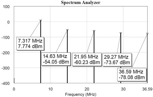
The two-stage oscillator is followed by a buffer amplifier
(Q3), which uses also a medium power transistor biased for linear amplification
to get minimum spurious emissions and harmonics. This amplifier is LC tuned on
oscillation frequency, and is followed by a steep 5 pole Elliptic Low-Pass
Filter (cut-off at 10MHz) to further reduce the harmonics.
Tuning the Variable Frequency Oscillator (VFO)
The feedback trim capacitor (C4) will be adjusted just to start and maintain the oscillation.
Any increase of capacitance from that value will increase the phase noise, due to loading of the tank circuit.
The oscillator can be used for other HF frequencies modifying in concordance L1, C1, C2, and of course the output LC tank L5, C13 and the LPF cut-off frequency if is necessarily.
To increase or decrease the frequency bandwidth covered by the VFO, C2 will be adjusted and if is necessarily a capacitor will be added in series with the variable capacitor C1.
Good quality inductors and capacitors will be used for good performances as frequency stability and phase noise.
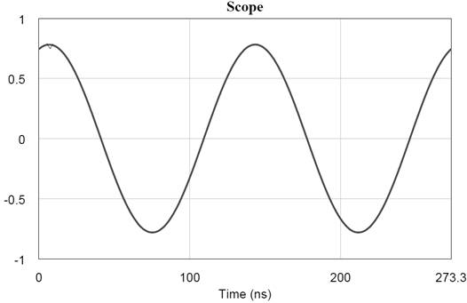
The output power of the oscillator is approximately +7dBm, ready to drive a diode mixer as SBL-1 or other mixers, adjusting the level in concordance.
R7 will be adjusted for proper input level of the buffer amplifier, below compression point, for perfect sine-wave and minimum harmonics at the output.
In conclusion a few criteria’s for minimum phase noise were met:
Used a BJT device (for low 1/f flicker corner)
Medium power transistors (for high parasitic capacitance to the ground)
Transistor with low fT (for low wideband noise)
Low current bias point (for low noise figure and low 1/f flicker noise)
Using Low-Pass feedback network (for noise cancellation)
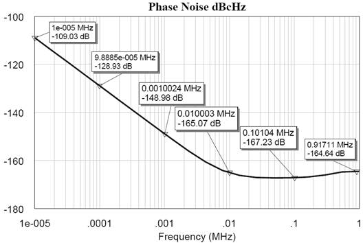
Below are a few simulated measurements of the VFO:
|
Phase Noise |
Offset from Carrier |
|
-109 dBc/Hz |
10 Hz |
|
-128 dBc/Hz |
100 Hz |
|
-148 dBc/Hz |
1 kHz |
|
-165 dBc/Hz |
10 kHz |
|
-167 dBc/Hz |
100 kHz |
|
-164 dBc/Hz |
1 MHz |
References:
1. LC Oscillators and their Frequency Stability - Tesla Technical Reports, Dec. 1949 - Jiri Vackar
2. Oscillator Design and Computer Simulation - R.W. Rhea
3. RF/Microwave Circuit Design for Wireless Applications - Ulrich L. Rohde and David P. Newkirk
4. Microwave Circuit Design using Linear and Nonlinear Techniques - G. Vendelin, A. Pavio, U. Rohde,
5. Oscillator Basics and Low-Noise Techniques for Microwave Oscillators and VCOs - U.Rohde
6. Low Noise Oscillator Design and Performance - Michael M. Driscoll
7. California Eastern Laboratories - AN1026 - “1/f Noise Characteristics Influencing Phase Noise”
8. Infineon Technologies - AN023 - Designing Oscillators with low 1/f-noise
9. Mini-Circuits – VCO Designers Handbook 2001
10. Applied Microwave and Wireless, 1997-2002
11. Analog Devices Application Notes
12. RF Design, 1993-2009
13. Microwave Journal, 1997-2009
14. Alpha Industries - VCO Application notes