January 2010: Our new repeater system build has been completed.
The new repeater consists of a Kenwood TKR-740, which is Kenwood's high performance
offering at the time of the rebuild, and a custom built 7 cavity TX/RX duplexer.
The 100 Watt Power Amplifier was scavenged from a commercial GE-MastrII base
station. We reused the circulator/isolator and ARR GaAsFET preamplifier
from the old repeater.
The repeater cabinet, power supply, and associated wiring was assembled by AA1PL
in his basement. N1JOY gathered an assortment of TX/RX Duplexer cans that
were donated to the group, and assembled them into a custom frame, built a
precision cut coax harness, and tuned this new 7 cavity behemoth to
specifications far beyond anything we had previously. All of the new hardware
was installed and tested at the site on Chopmist Hill, and the performance
numbers almost blew us away. Receive sensitivity was an amazing, 0.07 uV with
the transmitter huffing out a full 100 Watts with 80 of them making it to the
antenna port. We did encounter an issue, which we suspected existed before
the rebuild, with what appears to be a bad coax connection at the top of the
tower. This is generating intermod and causing RX desense. A
temporary reduction of the TX power was done to help increase the usability of
the repeater until we can gain access to the top of the tower.
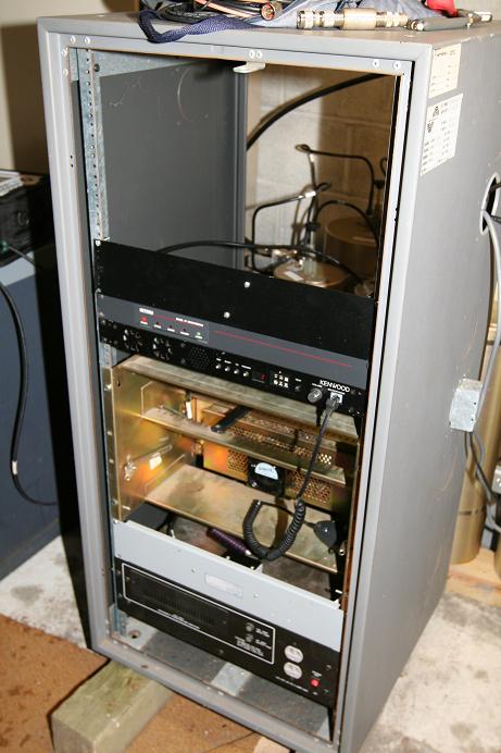
This is the 146.760 repeater cabinet as of January 2010.
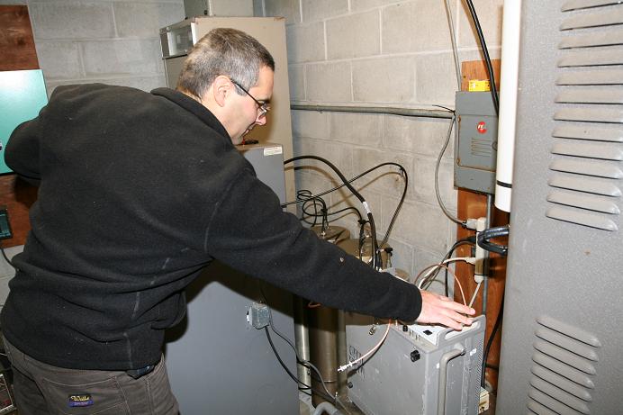
Here is AA1PL testing the new repeater performance.
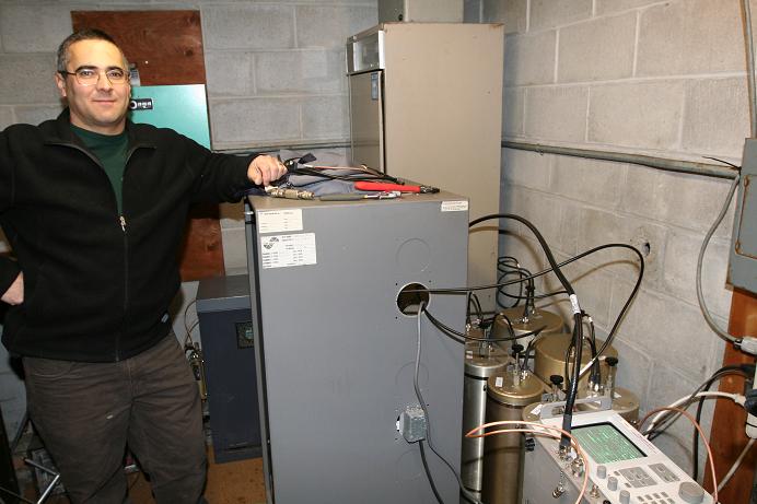
AA1PL takes a moment to pose with the new hardware under test. Behind the
repeater cabinet you can see half of the new duplexer.
Originally, the repeater was on 146.70 MHz and located in Woonsocket, RI. There was also a repeater in Cranston, RI on Phenix Avenue on the same frequency, owned by K1ABR (now W1XJ). Both repeaters were basically local area coverage only, so there was little co-channel interference.
In 1971, John Laramee WA1OZF, through his contacts, was able to get us a site 9 miles north of Providence on a hilltop in Lincoln, RI. The equipment back then was pretty basic consisting mainly of converted trunk mounted taxi-cab/police transmitters and receivers. The controller was built by George Carnegis K1BCT and Bob Moio K1RAT (now K1RAM) at Brown University. George and Bob are both engineers.
The duplexer was designed by a ham in Salem, MA, which we duplicated and fondly referred to as "The Witch". Arthur Pelchat WA1PQX (a former board member now a silent key), manufactured the cavities in his machine shop, and Dick Bouchard, W1HQV, put them together and placed them on line. The antenna we used was a commercial Phelps-Dodge, (now Celwave), fiberglass encased Station Master vertical providing about 5.2 dBd of gain. The transmitter put out about 25 watts on a good day, and our effective radiated power (ERP) was 47 watts. One unique feature of the system was our time identifier made from a Panasonic voice type clock radio, which announced the time of day in a female voice whenever the CW identifier triggered. Our talking clock pre-dated voice synthesizer designs of today and consisted of two rotating magnetic tape discs. The outer disk had the hours recorded on it and the inner disc had minutes on it. The playback head scanned across the surface of the discs when the time was transmitted. We called her "Frosty" since the device was kept in the freezer compartment of our high-tech repeater enclosure, an old Coldspot refrigerator located at the base of the tower.
Soon after the move to Lincoln, the FCC came out with their new, complicated repeater licensing regulations. After much work and correspondence, the application went to the FCC, and some time later we received our new call sign, WR1ACE. Many users called it "New England's Ace repeater"! As good as the location was, it was not without its unique problems. The most consistently aggravating was interference (site noise) from the RF ovens at the Owens Corning Fiberglas plant in Ashton across the river from the site. Many times communications were impossible due to the horrific noise and time-outs were frequent.
Around 1977, Dick W1HQV, and Mike Chorney K1ICI (now a silent key), were able to secure the current site 13 miles west of Providence in Scituate on Chopmist Hill (724 ft. ASL). They acquired a surplus 120 foot tower to erect at Chopmist, putting the top of our antenna at 844 ft. ASL. Coverage instantly improved with the new site even with the relatively low power used. Also, the call sign of the repeater was changed at this time to W1HQV, and remains until today.
In 1985, K1KYI and WA1POX attended a flea market in Topsfield, MA and met a ham from New Hampshire who was selling a modern (by our standards) Motorola base station. It had been converted for amateur use by hams at the Motorola employees ham club in Chicago and was lower power version of the repeater in use for the 146.70 repeater in Cranston. The following week, we purchased the repeater. Steve Anthony WA1POX, brought it to his home for testing and tweaking and K1KYI ordered crystals for the channel elements. It had a capability of 125 watts out of the transmitter and was a "hybrid", meaning it used tubes and solid state components in the transmitter. The receiver was totally solid state. Unfortunately, the service life of the ceramic type final amplifier tube proved to be fairly short. We found that replacement was needed often and replacements didn't come cheap...they were $160!
Finally in 1988 we decided to purchase a model 4111 solid state power amplifier from Falcon Communications which would eliminate final tube replacement costs and hopefully provide more reliable service. It was capable of producing up to 120 watts output, but we ran it at around 95 watts most of the time. It proved to be fairly trouble free.
At the '76 auction in the fall of 1996, our good friend Tom Olsson WA1YSN, (now W1TKO), donated to us two surplus Motorola Mitrek solid state 100 watt output mobile radios. We gratefully accepted these, and Pete Harrison AA1PL, volunteered to convert them over to repeater use, since by now the base station was requiring more and more maintenance. Peter spent a great deal of his "spare time" in his basement workshop building the new repeater. In April of 1997, Peter, Steve Anthony WA1POX, and Rick Fairweather K1KYI, brought it to the site and put it on the air. Aside from some persistent problems with the Micro Computer Concepts controller, (which has since been replaced), and some problems with the power supply, it has been running fine ever since. Trips to the site these days are very infrequent!
The current repeater is built mostly from commercial equipment. The receiver/transmitter is a Motorola Mitrek 100 watt mobile transceiver which has been modified to be full duplex (able to transmit and receive simultaneously). It is supported by a 4 can Wacom BpBr duplexer, EMR isolator in the transmit line, ARR GaAsFET pre-amplifier, additional band pass filters in the receive line, a Zetron repeater controller, and a Astron 35A power supply with built in volt/ammeters. The repeater is housed in an old GE base station cabinet with a service microphone and speaker. The antenna is a commercial grade Radio Frequency Systems PD-220 Station Master with 5.5 dBd gain and is fed by 7/8 inch diameter Heliax transmission line.
A spare full duplex Mitrek transceiver kept at the repeater site and can be quickly put in to service if the primary one should develop problems, although this is rarely needed due to its' great reliability. We presently do not have any "bells & whistles" on the repeater, but instead offer a reliable, wide-area machine. The repeater operates with COS (Carrier Operated Squelch) and does not require a PL tone. Having no PL can occasionally be a minor nuisance, but many times during the Summer it is a lot of fun to work other Hams from all over the East Coast during strong band openings (tropospheric ducting). Occasionally you can hear Hams from Canada to Virginia, and sometimes farther!
In September of 2006 we did a major overhaul of the antenna system. A brand new Station Master antenna was donated by N1JOY, along with a new length of 7/8" Heliax and connectors. The old antenna and coax had been steadily deteriorating, and coverage had been suffering. When the new antenna and feed line were installed, the repeater came to life better than anybody could remember in recent years. During this rebuild, several RIAFMRS BOD members spent the day cleaning out the repeater shack and tossed a good sized pile of old obsolete equipment that was no longer usable. Ray Stanford N1CYX, who owns Telecast Tower Works, did the difficult task of climbing the monopole tower, stripping all of the old antennas and spare hardware, then installed 4 new antennas and feed line runs for 146.76, 223.76, & 447.425, and a spare dual band antenna half way up the tower.
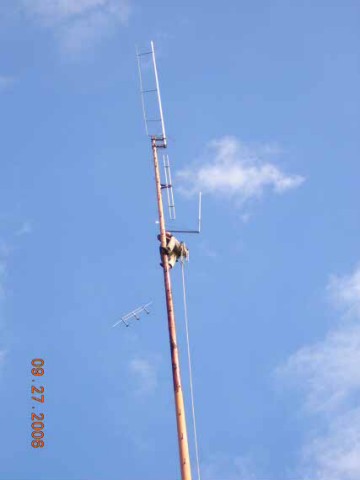 | 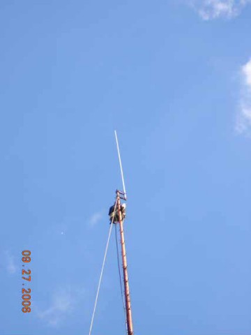 | |
Ray N1CYX stripping all of the old antennas and hardware off the monopole tower. |
|
146.76 Coverage Map
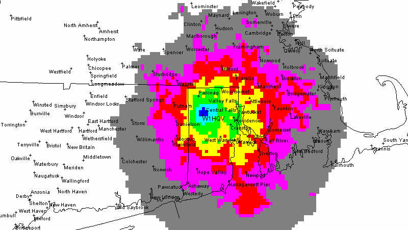
The map shows the different signal intensities for talk out. The gray area is signals between -89 and -119 dBm.
In the real world, the violet is pretty much the limit for reliable mobile coverage, but the repeater can be worked
from high spots throughout the gray area also.
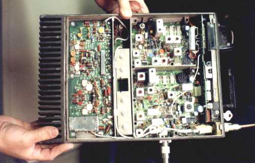 | This is the Motorola Mitrek transceiver which was modified for full duplex operation. The top corner is the transmit exciter section. The 100 watt power amplifier is on the left side (note the Heavy Duty heat sink). The receive signal comes in through the antenna jack on the bottom of the photo, and passes through the 5-pole helical front-end filter (center) before entering the receiver section (lower right). All external connections, (controller, DC power, volume/squelch controls, service mic/speaker) are made through the large connector on the upper right of the photo. |
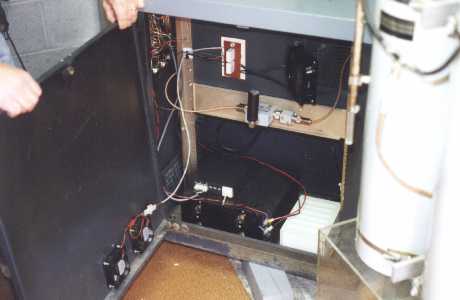
| This shows the inside front view of the repeater. The Mitrek transceiver is at the top. The cover is cut out over the P.A. to allow for a fan on the cabinet door to blow cool air onto the P.A. components. Below the Mitrek is the ARR GaAsFET receiver pre-amp. At the bottom left is an AC line conditioner. The Zetron repeater controller sits on top of the Astron power supply in the lower right. |
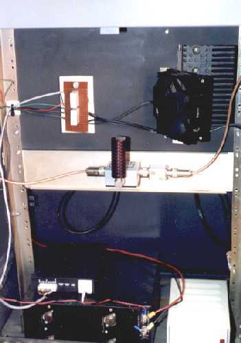 | This shows the inside back view of the repeater. The rack panel holding the Mitrek transceiver is cut out behind the P.A. heat sink to expose it to another cooling fan. Below the fan is the transmit isolator (used to prevent transmitter inter-modulation). The rear of the power supply and repeater controller are shown on the bottom of the photo. |
| This is the repeaters duplexer. This allows the repeater to transmit on the 146.76 frequency while receiving on 146.16 simultaneously using one antenna. Each 'can' is a very high-Q resonant filter. The left side passes 146.16 receive signal while rejecting the transmitted 146.76 signal, while attenuating spurious energy on the 146.16 receive frequency. The antenna connects to the duplexer at the center T-connector. |
| Forced air cooling is important on the transmitter's amplifier as well as the power supply. This photo shows two 3-inch fans mounted in the cabinet doors and positioned to keep the power supply cool when the door is closed. Another 4-inch fan is mounted on the front cabinet door and it keeps the power amplifier cool from the component side. |
![]()