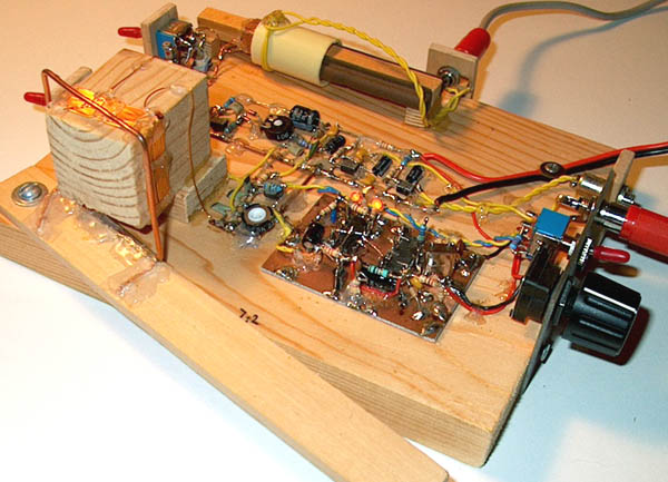
Simple SSB-CW receiver with a modified frequency
stabilizer for PSK31 reception and fine tuning.
MODIFIED FREQUENCY STABILIZER FOR PSK31
RECEPTION WITH THE SIMPLE RECEIVER
(2008)
KLIK HIER VOOR DE NEDERLANDSE VERSIE
Simple SSB-CW receiver with a modified frequency
stabilizer for PSK31 reception and fine tuning.

The new version of the receiver with fine tuning, 30 meter
band and a connection for the soundcard of the PC.
big diagram
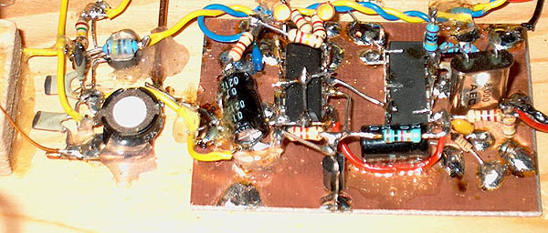
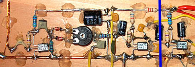
Modified simple frequency stabilizer and VFO.
The frequency stabilizer with fine tuning.
big diagram
The working principle of this stabilizer is very simple:
In fact it is not a frequency stabilizer but a phase stabilizer. The D-input of a D-flipflop is connected to the VFO signal. The clock input is connected to the clock signal of 976 Hz. On the rising edge of the clock signal, the output is set to the value of the D-input. So a "1" when the clockpulse goes high at the positive part of the sine of the VFO signal, a "0" when the clockpulse goes high during the negative part of the sine of the VFO signal. The output of the D-flipflop controls the VFO frequency via a kind of PLL loop filter.
 Reception of the 10 MHz calibration signal without stabilizer during two minutes. Drift already 60 Hz! |
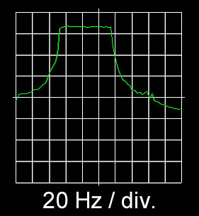
 Reception of the 10 MHz calibration signal with stabilizer during half an hour. Drift only 2 to 3 Hz! |
Without frequency stabilizer, the receiver drifted approximately 60 Hz during two minutes, sometimes already 10 to 20 Hz during a few seconds. With frequency stabilizer, the drift during half an hour was only 2 to 3 Hz at 10 MHz! It was very simple to measure the drift. The receiver was tuned to the 10 MHz signal of my simple frequency standard and the frequency of the LF output signal of the receiver was measured with the soundcard of the PC and an audio spectrum analyzer program.
The loop filter
The frequency control is very simple, it has two settings: Full speed upwards or full speed downwards. So a loop filter is required to slow down and damp this extreme frequency control. Choose the values of Rx and Cx so that the control is stable and you do not hear many irritating sounds while receiving CW signals. It is possible to tune in smaller steps when you do use the clock signal of Q14. But stabilization is less good then. Cx has also to be increased to 100 uF and Rx has a value between 68 and 120 ohm. But these values can be totally different in your circuit!
The first experiments were not a success. The solution was simple, I had chosen the wrong values for Cx and Rx, and that was the reason why the frequency control did not work.
The lock indicator with two leds.
Adjust the potentiometer so that they are equal in brightness.
Then the stabilizer is in the centre of the control range.
A VCO without varicap
Usually we do use a varicap to control the VFO frequency. But we can do that without a varicap.
Fine tuning can be done by just varying the voltage of the base of the transistor T2 via a 1M resistor with a 10k ohm potentiometer. The tuning range is approximately 60 kHz and I cannot explain why, but it is almost equal on all bands! This method of varying the frequency without using a varicap is used to control the VFO frequency by the frequency stabilizer!
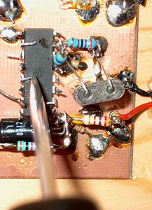
Free frequency marker generator! Just touch
a pin of the 74HC4060 with a screwdriver.
When the receiver is connected to the soundcard of the PC, you do not
need the final LF stage of the original receiver (right side of the blue line).
Results
With the frequency stabilizer, PSK31 reception is good. With the lock indicator (the 2 leds), you can check if the stabilizer is within the control range. For reception of SSB and CW, the frequency stabilizer is switched off. The frequency steps are too large for SSB and CW and the stabilizer causes still some weak but irritating audio sounds. But the VFO is stable enough for the reception of CW and SSB. The fine tuning works perfect, tuning to SSB stations is very easy.
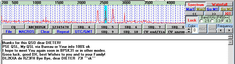
Reception of PSK31 with the MultiPSK program of
Patrick F6CTE goes excellent with the frequency stabilizer!
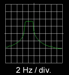
ARGO, a program for the reception of QRSS beacons with very low power
To make a QSO with very low power, that must be very interesting for us, QRP'ers! A few radio amateurs are active with transmissions with very low power, less than 100 mW. And they do make QSO's with all continents with such low power! That is possible by using a very low CW speed in combination with a special computer program such as ARGO. The CW speed is very low, 1 dot lasts 1 to 3 seconds. The frequency stability of the transmitter and receiver has to be very good. But this simple receiver with frequency stabilizer is certainly very stable!
Unfortunately, there were no active stations. But I could use a professional RF generator to test how much better such a QRSS signal can be received compared to normal CW signals.
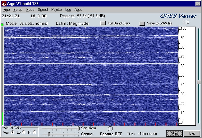
Reception of QRSS signals with the ARGO program.
The 31Hz line is the weak testsignal.
It is very nice to play with this program. I made a connection for a frequency counter at the frequency stabilizer, so that it is possible to measure exactly the reception frequency. Also the souncard has to be calibrated. My card had an error of approximately 20 Hz at 1 kHz. For the calibration, you can use the 976 Hz clocksignal. Touch this signal with you finger and you will see it on your ARGO screen.
And again we had much fun with a very simple radio circuit!