Simple SSB-CW receiver for 20 and 40 meter.
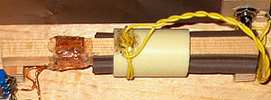
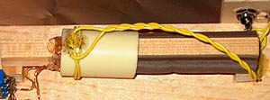
Tuning mechanism is made of a wooden stick and a shortened
winding of copper wire, moving to the VFO coil.
Rules for the homebrew competition of a shortwave receiver
SIMPLE RECEIVER FOR 40 AND 20 M
WITH AN UNUSUAL TUNING CONTROL
(2007)
KLIK HIER VOOR DE NEDERLANDSE VERSIE
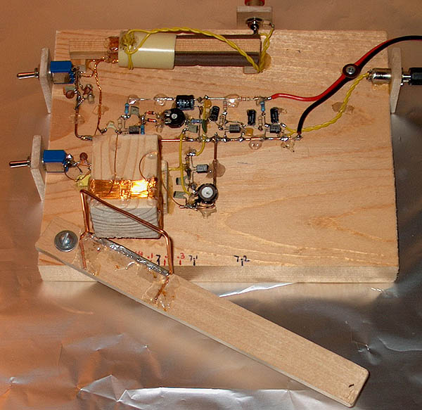
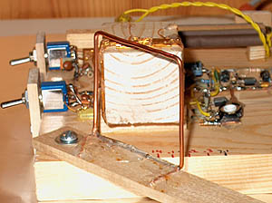
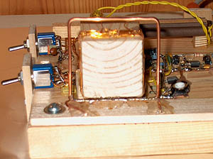
Simple SSB-CW receiver for 20 and 40 meter.
Tuning mechanism is made of a wooden stick and a shortened
winding of copper wire, moving to the VFO coil.
The volume control is an antenna coil on a plastic tube that can be moved to- and over the input coil. The electronic circuit is soldered on a piece of thick copper wire (ground) and glued to the wooden chassis with a glue gun. You can also melt the glue sticks with your solder iron. New components, a solid wooden chassis, a big chance that this receiver will still work after 30 years!
A day and a night band are chosen, the 20 and 40 meter band. The 40 meter band is also an excellent test band for the receiver due to the very strong broadcast stations directly above this amateurband (in Europe!). And on 20 meters you do need already quite a good frequency stability, so also a good test for this simple receiver.
For the starting home brewer!
A starting home brewer can easily make this receiver. The hardware layout is almost equal to the layout of the schematic diagram, so it is very easy to compare the hardware with the schematic diagram. Although the performance is not superb, you can hear very much with it. It is also a nice receiver for many interesting experiments. The electronic circuit is developed in such a way, that not much will be damaged when you do make a mistake. Only for the alignment you will need perhaps some help. You will discover that this receiver does have some disadvantages like many other simple direct conversion receivers have. But there are also very good direct conversion receivers that do not have these disadvantages!
Schematic diagram of the receiver for 20 and 40 meter
big diagram
Low volume |
High volume |
RA3AAE mixer
One of the diodes conducts during the positive half period of the sine of the VFO signal, the other diode during the negative half period of the sine. But due to the voltage drop of approximately 0.7 V, the diodes will only conduct during the positive top and the negative top of the sine and not near the zero crossings of the sine wave of the VFO signal. So they do behave like a switch that switches 2x on/off during one sine period of the VFO signal. That is why the VFO has to work on half the reception frequency! The level of the VFO signal is very important. When the VFO signal is too high, the diode switch will be switched on almost continuously. When the VFO signal is too low (below 0.7 V), the diodes will not conduct. You will have the best result when the "on" time is almost equal to the "off" time. The correct level can be adjusted with P2 by ear.
For a good operation of the mixer, the impedance at the input has to be rather low, 470 ohm turned out to be a good value. The 100 pF capacitor and the 470 ohm resistor are also a high pass filter that rejects the low frequency noise from the RF amplifier.
The mixer was rather sensitive for strong Amplitude Modulated signals, although they suggest that it should not be so... A reason is perhaps that the properties of the diodes are not equal or perhaps that the VFO signal is not a perfect symmetric sine wave or the simple design of the electronic circuit. But adding P1 and a correct adjustment of it by ear does reduce that sensitivity for strong AM signals considerably.
VFO
A VFO without a variable capacitor! A very nice solution is the one Wayne Mc Fee NB6M is using in its Tin Ear receiver. A brass screw moves like a core into and out the VFO coil. But it is always interesting to try something else. So here a wooden stick with a shortened winding of copper wire is used, This shortened winding moves to the VFO coil and that is how the frequency can be varied! The range is too large, on 40 meters from 6750 kHz to 7450 kHz and on 20 meter 13700 kHz to 15100 kHz. I did not change it, but when you make it smaller, tuning will be easier. Reduction of the tuning range can be done by increasing te diameter of L4 and/or reducing the diameter of L3, the VFO coil. You can make a simple frequency dial: Note down the corresponding frequency where the wooden stick touches the wooden chassis.
Except sensitivity for strong AM signals, many direct conversion receivers do have the problem that much VFO signal reaches the antenna input, certainly at such an open unscreened construction as is used here. And that will cause a loud 50 Hz hum signal in the receiver. That is why you have to place S1 and S2 quite far from each other. Do not combine them in 1 switch. The RF preamplifier has two important functions, increasing the sensitivity and attenuation of the VFO signal from the mixer to the antenna. A big advantage is that the VFO signal for the RA3AAE mixer is on half the reception frequency. The VFO signal from the mixer to the antenna is extra attenuated by the selective tuned input circuit.
Low VFO frequency |
High VFO frequency |
LF amplifiers
The resistor of 220 ohm and the capacitor of 100 uF are a filter for the supply voltage for the RF amplifier, VFO and first LF amplifier T3. Noise and hum from the 12V power supply are suppressed by this filter. An elco is a bad capacitor for RF signals, therefore a 0.1 uF capacitor is connected in parallel to it.
The weak LF output signal from the mixer is amplified considerably by T3 and T4. The transistors are set by the resistors of 1M ohm and 470k ohm between collector and base. The capacitors of 47 nF and 10 nF are an audio low pass filter. If you want to change the selectivity, then just change the value of these capacitors.
The two earpieces of the headphones are connected in series to get a higher sound level. Interesting is that there is much difference in quality and sensitivity between different headphones. The HS415 of Philips is the best, very sensitive and excellent sound quality. Most headphones like the one I use for my PC, are good enough. But cheap earplugs were very bad, bad sensitivity and a bad audio quality.
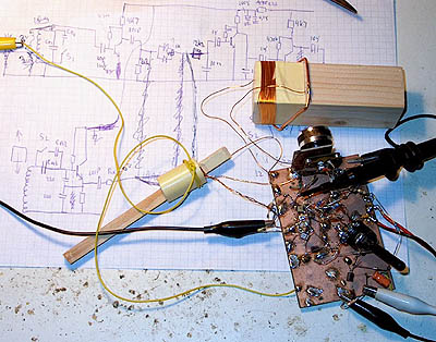
The prototype.
On my buro with metal frame, I have to use a piece of aluminium foil connected to ground below the receiver. Without the aluminium foil, I do hear some hum in the LF amplifier and the VFO is considerably frequency modulated with 50 Hz.
PSK31 reception was not possible, because the VFO frequency was influenced too much due to the open unscreened construction.
This receiver works quite good for such a simple thing. It is a pity that there is sometimes some interference of strong AM broadcast stations and that it is not possible to receive PSK31. But it is simple and easy to construct and only very ordinary mechanical and electronic components are used!