Start with building the Taurus Transceiver
10 December 2012
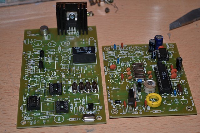
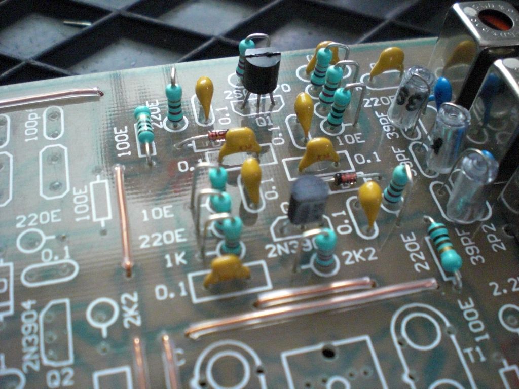
"Started with the building of the Taurus TX, 3.5 Watt
qrp SSB transceiver"
The transceiver is design on two PCB's and designed by SP5DDJ
(see links page).
The PCB's can used for 20,40 and 80 meter homemade TX.
A few parts you have to change to change the basic Ham-frequency.
In polish you can find an easy manual with the basic steps and also a
checklist for the needed parts. When follow the 'installation' manual
you will get a nice small QRP transceiver.
Their are a few mods for the basic-PCB .. when finished the building I
will place them in the download section. In the meantime you can see a
few
at - http://pa-11019.blogspot.nl
- the hamsite of PD7MAA.
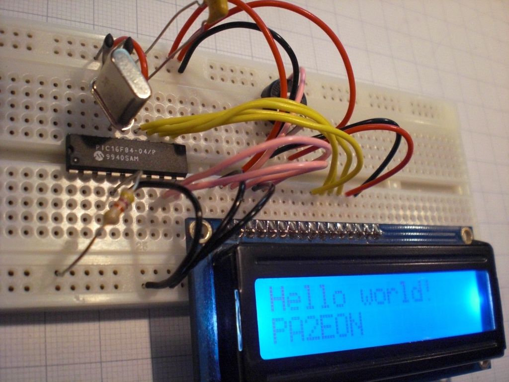
Click on the photo to see the full size !
pic
a.
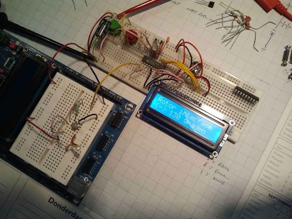
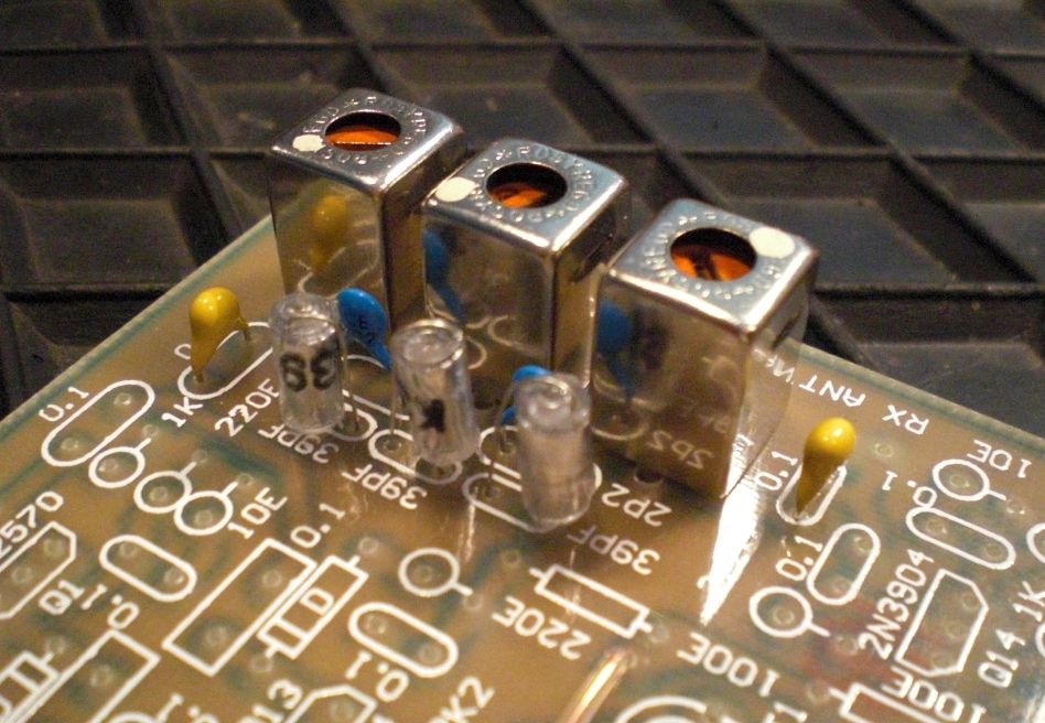
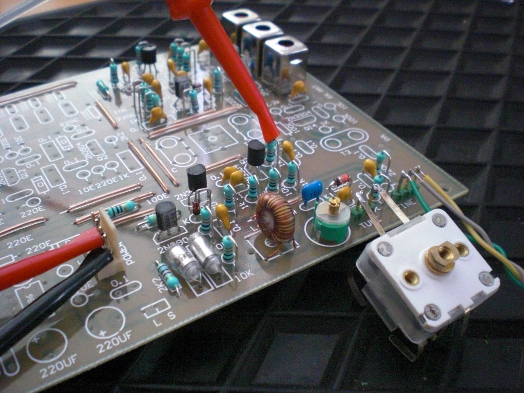
26-12-2012 UPDATE - Receiver is ready !
Today
the receiver is ready in his first stage. So far known the mods are
used and the first QSO is recorded (see *.mov). The next step is
de finetuning to hear the stations more easy, have to check the filters
and potmeters!
 Movie of the Receiver board
pic b.
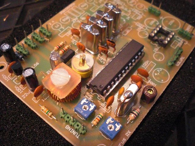
Needed PC-scope - start to collect hardware!
29 April 2012
"For the project of the Taurus & Bitx 20m
trancievers ..we need more to see"
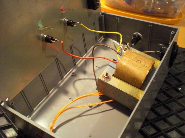
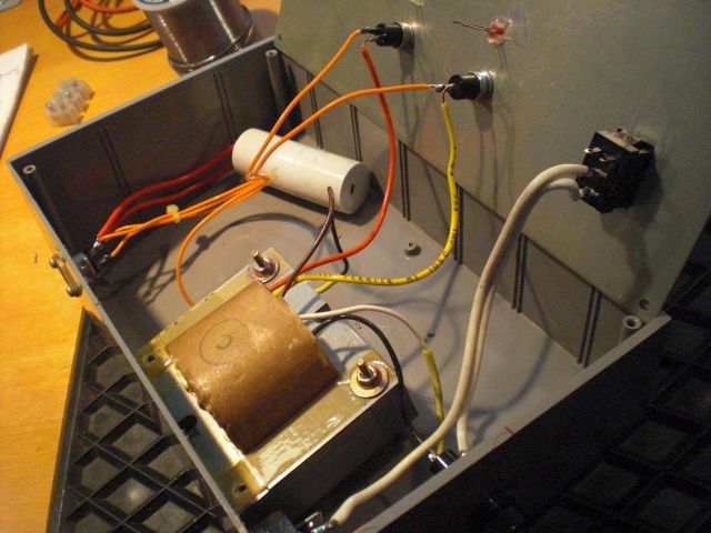
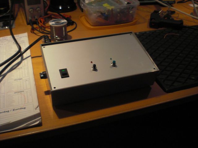
The next pictures will give the first view of the nice small
box, and the first small
parts
we have collected. The box I found in the 'junk-box' is a case what I
find on one of the dutch flee-markets in the Netherlands .. never used
before!
The PCB design will be made and the schema is from 'Tim Witham - 1996'
I have removed the pictures,
because the PC-scope will give no good results.
The box I'am going to
use for the new Taurus transceiver !
The range of the PC-scope is between 20Hz - 22 kHz.
We
need more ... what will be the best schema for this, the beta test
looks oke but to see what is going on in the range 20 Mhz to 50 Mhz we
need other hardware!
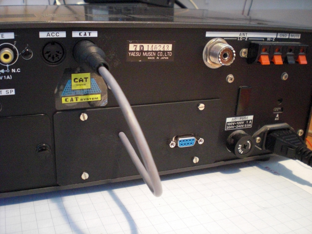
Finished the CAT-interface
for the FRG 8800 Receiver. This
small
project is easy to make I used the schema from J.F. Kok with the MAX
232 and his 'special made' software to handle the RX.
The
interface is made in the 'open space' of the 144 Mhz
transverter
who is not in my RX .. if you have installed the 'transverter' you have
to made an external box. The power for the interface, will get from the
RS232 connection of the PC.
Pictures of the project:
 Copyrights:
website
of J.F Kok
.: The schema of the interface.
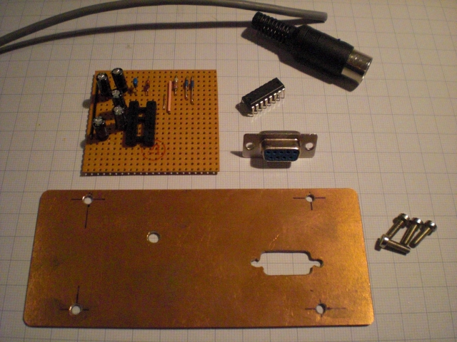
.:
All parts.
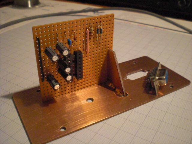
.: Base position.
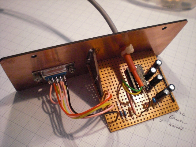
.:
Interface ready.
.: Operational.
Right click on picture to show large (640x480p) ..