De PA0SNY/AM explanation page
This page is not in Dutch
(Deze pagina is dus niet in het Frans of Duits)
| Some
details of HF on the A330 (747 is similar) |
The purpose of this page is to give some background on the HF equipment installation
on the Airbus A330. I will not go into deep details, but will try keep it simple yet informative.
Basically the A330 has 2 HF systems, each consisting of an HF transceiver. This is the
Rockwell Collins model HFS-900 with p/n 822-0330-020.
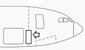 |
Both transceivers are mounted in the avionics compartment, an area just forward of the forward cargo compartment. |
The HF transceivers are controled from the cockpit. From three so called RMP's.
These are the Radio Management Panels. From these panels the 'radio' is selected
(HF1 or HF2) and the desired frequency is selected in the 'standby' window. After
that this frequency is transfered to the 'active' window. When pressing the PTT on
the microphone, the antenna coupler matches the transceiver output to the antenna.
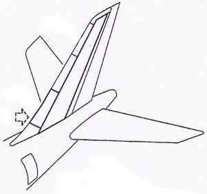 |
From the Avionics Compartment, 52 ohm
coaxial cabels run to the tail of the aircraft. On the lower part of the vertical tailplane, the HF antenna is mounted on isolating studs on the front spar, behind a composite nose. |
The output of each antenna coupler goes directly to a piece of metal: the exiting plate.
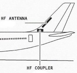 |
Here a pictorial display of the
approximate location of the couplers and the exiting plate, here
mentioned 'antenna'. In fact the coupler provides low voltage / high
current RF to this plate, which in fact makes the vertical tail of even
the entaire aircraft as an antenna. The wing tips on older 747's and the probe on even older 707 vertical fin, have the same principle. |
|
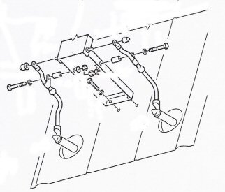
| The direct coupling of the two couplers is
here well visible. The connecting cable from the coupler (at the
lower side if this picture) is fixed on the isolating stud
mechanically, and attaches to the metal piece that we now know as 'the
exiting plate' that is fixed to the vertical tail structure |
 |
|
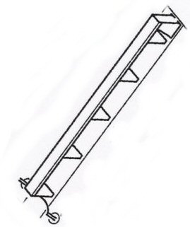 |
The situation on the tail's front spar:
the whole exiting plate. The length is around three and a half meters
(so 10
feet) only Note: on the 747 classic it is the stick in the wingtip! Same size.
|
And finally an overview of the HF system. You see here the 'essentials' of the systems.
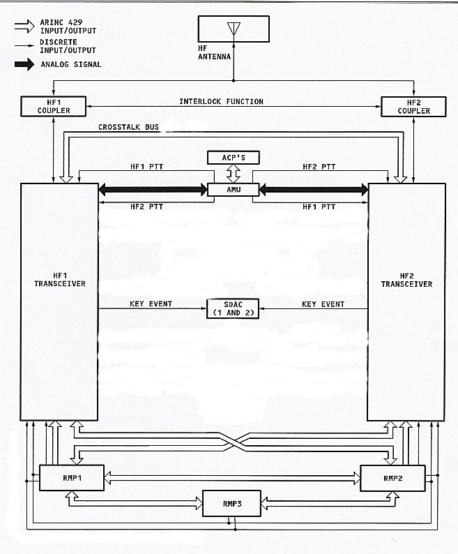
RMP
=
Radio Management panel, one for each pilot and a third for the observer
AMU = Audio Mangement Unit: arranging audio for all equipment on board
ACP = Audio Control Panel, one for each pilot and a third for the observer.
AMU = Audio Mangement Unit: arranging audio for all equipment on board
ACP = Audio Control Panel, one for each pilot and a third for the observer.
On
the AMU the HF system is selected 'on' and the RX volume is being set.
The AMU has a
switch to PTT the (HF) system. This switch is doing the same as the PTT switch on the
microphone. Because of my position in the cockpit under such circumstances (on the 'fourth
seat, behind the pilot on the right hand side) I prefer to use the PTT on the hand microphone.
Back to the SNY-AM page
switch to PTT the (HF) system. This switch is doing the same as the PTT switch on the
microphone. Because of my position in the cockpit under such circumstances (on the 'fourth
seat, behind the pilot on the right hand side) I prefer to use the PTT on the hand microphone.
Back to the SNY-AM page