Before we start to assemble our traps, here some general info as introduction :
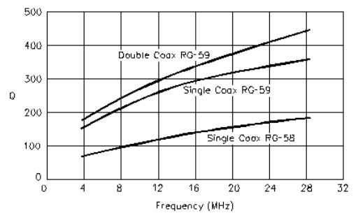
So they are definitelymore 'lossy' than air wound coils with high
quality capacitors, but:
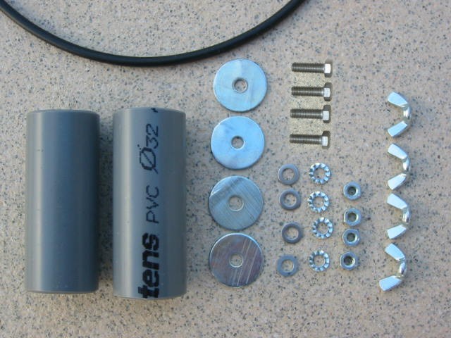 |
Bill of Materials (for 2 traps):
|
|
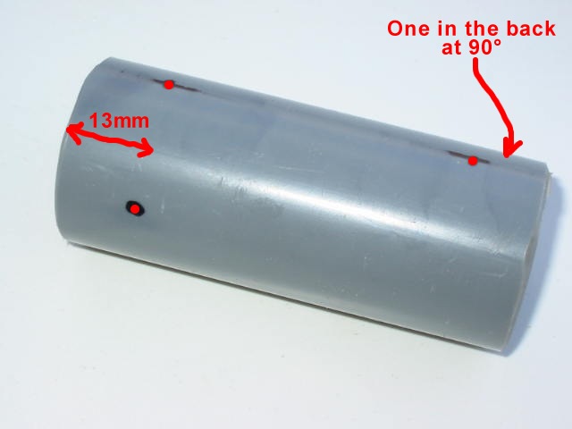 |
Preparation of the pipes:
|
|
 |
Drill all 4 holes with 5mm and remove sharp edges with a trimmer, especially for the coax holes | |
 |
Preparation of the the 4 big washers:
|
|
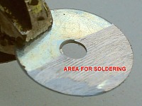 |
Now this will be the area where we will solder the coax ends | |
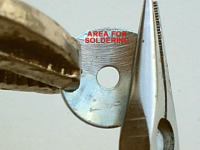 |
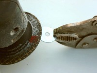
Using 2 pliers, bend the washer so that it will fit inside the PVC tube. Keep the area for soldering as depicted! | |
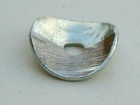 |
This will be the result (4 pces), adjust till they nicely fit inside the PVC tube. | |
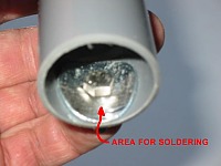 |
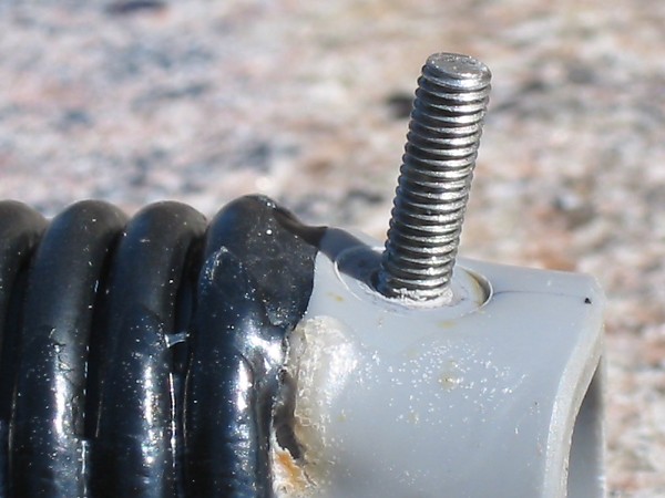
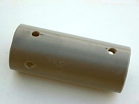
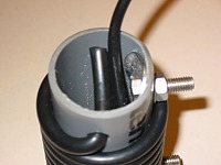
Now insert the 4 big washers in the tube ends, keep the area for soldering on the outer side, and insert the M5 bolts. | |
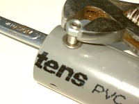 |
Now put the small washer and M5 nut on the bolts
and tighten very well with appropriate tools. We are now ready to start to wind our coax coils ! |
|
 |
Take 93 (153) (67) cm of RG-58C/U coax for each coil. Insert approx 10 cm in the hole for the 'start'. RG-58C/U will just pass in a 5mm hole. | |
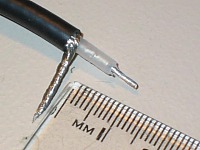 |
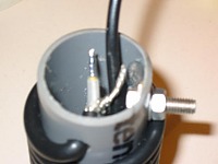
Remove insulation on 15mm of the end passed through pipe and prepare tail like shown | |
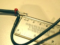 |
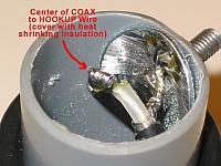
On the shield, solder a small hookup wire length 120mm about (take at least same gauge as coax center wire) and cover with heat shrink tube. Put a small nylon fastener 3mm after the start of coax outer jacket (here in the picture in red). |
|
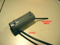 |
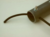
Now gently retract the coax in the tube, while inserting the hookup wire till it comes out of the tube on the other side, and the coax cannot be pulled out any more (nylon fastener) | |
 |
Now solder (a 60w iron should be OK) the coax center on the big washer. Make sure you have a good bond, but do not overheat as the coax / PVC will melt... | |
 |
Now start to wind the coil !
|
|
 |
Use the short remaining end of coax to pull is as much as possible inside the tube and have windings sitting tight. Then cut off the coax so you have 20mm left inside the tube. | |
 |
Using a cutter knife delicately around outer jacket, remove insulation on about 15mm and prepare coax ends like shown. | |
 |
Your coax trap is now ready to be tuned ! |
|
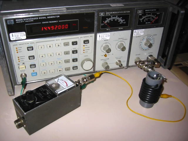 |
How to tune the traps ?
|
|
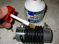 |
Once the resonance is OK and the trap is looking fine, apply PVC glue (this glue is used for mounting PVC tubing, it is clear, dries in minutes and becomes quite hard after hours) on the windings, especially on the outer turns of the coil, and a couple of strokes in the longitudinal direction. Liberally apply 2 or 3 coats of glue as well on the coil inside (soldering points, coax ends, big washers etc. to weather protect these elements). The recheck the resonance point : it will not have moved due to the glue. |
|
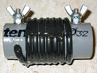 |
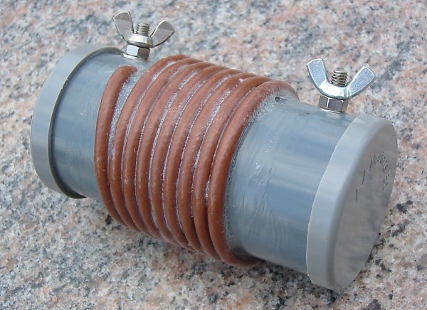
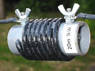
Put the 5mm 'grower' washers and the butterfly nuts in place (with some Vaseline grease as protection against rust) : your COAXTRAP is now ready ! Apply a label indicating the band it has been designed for as the 'finishing touch' ! |
See my '' simple HF holiday antenna's '' page
to make your dipole !
Very useful links: |
||
| http://www.w8ji.com/traps.htm | Calculation of trap losses under various conditions by W8JI Tom | |
| http://degood.org/coaxtrap/ | The attic dipole with coax traps for 80 to 10m by NU3E John | |
| http://www.qsl.net/ve6yp/index.html |
Coaxtrap.zip : Coax Trap calculator / designer by
VE6YO Tony (see below) |
|
|
|
||
Some additional info... |
|
|
|
|
|
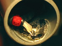
Melted and short-circuited
20m trap... power 800w SSB. |
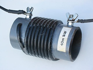
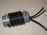
40m high power trap with RG-400 teflon coax |