Steps from a prime focus dish to an offset dish. Input and output parameters of the program.
E M E - antenna
My first dish I had built back in 1979. It was a 2m prime focus for tropo use. Some more were following with sizes up to 11m, so I could collect experience. Looking for a new challenge, I finally started a special project....
Several years ago I had experienced very good results
of EME stations using offset dishes, especially on receive. This can be easily
explained by well-known reasons: There is no blocking by the feed, and because
of a more upward-looking feed, the spillover picks up less ground noise.
(See also my presentation at the EME2014 conference in France: hb_offset_jfl.pdf
. The content is similar to this webpage)
To learn about the improvements in practice, I extended the upper part of a
2.8m prime focus dish. The performance was quite good, so I presented this project
and its results at the 2012 EME conference in Cambridge.
But in fact this was more or less a startup project, as I was already thinking
about building a larger offset dish. Of course blocking by the feed has less
influence the larger the dish is, but the advantage of less spillover noise
pickup by the feed is still present. A large dish also has the convenience of
an easy access, as you have the feed close to the ground.
An additional reason for starting this project was that (as far as I know) no
member of the EME community has built a large offset dish himself before. ;-)
A prime focus dish is relatively easy to build. You only need one simple formula,
choose the diameter and the f/D ratio, and you can calculate the dimensions
of the ribs, which all have the same shape.
The story is completely different with the offset
dish. As the mechanical center of the dish is now outside the vertex, the curvature
and the length of the ribs are different. Only right and left side are identical,
which results in pairs of ribs of the same shape.
I had hoped to find a helpful formula in some antenna book or on the internet
for designing a dish fitting into all desired parameters, but I wasn't lucky.
So although I do not like programming at all, I had no choice…
The instrumentation and visualization software Labview is not the very best
for calculating the ribs for a dish, but I am somewhat used to it and it contains
all the mathematical functions needed for this project.
The results of the calculations seemed reasonable, but to be honest, I did not
totally trust my own formulas. Therefore I decided to build a model, covered
the surface with aluminium kitchen foil and placed a small strong LED at the
focus. I could observe a nice light spot at the wall in the predicted direction.
Later I simulated the offset dish including the feed with NEC to have an additional
confirmation. The main lobe and also the gain from the simulation fit my expectations.
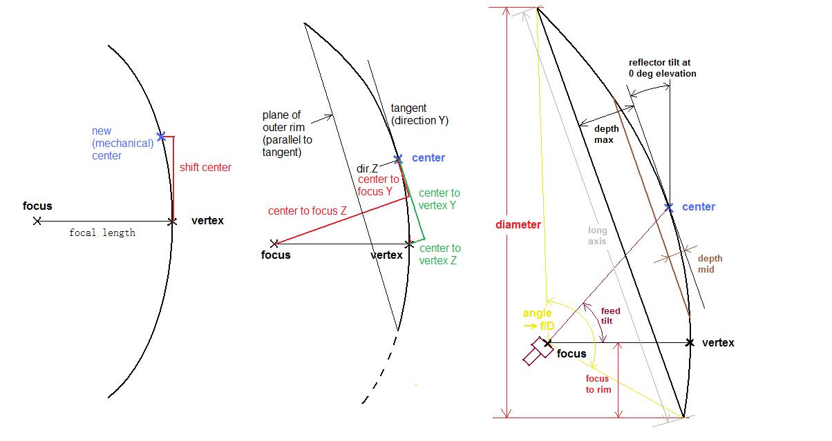
Conventinal prime focus dish designs usually have the mechanical center (hub
for fixing the ribs) at the vertex of the paraboloid. With my program 'Ofs_calc_jfl'
I can choose the focal length, the depth of the dish, and then shift the mechanical
center upwards to achieve an offset dish. The program provides the rib dimensions
as a chart.
Steps from a prime focus dish to an offset dish. Input and output parameters
of the program.
If the focus at 0 deg elevation is not higher than
the lowest point of the rim, it is a true offset ( 'focus to rim' < = 0 ).
In the case of ( 0 < 'focus to rim' < diameter/2 ) the dish is more or
less offset, which you can consider as a hybrid.
I suggest to change the parameters 'focal length', 'depth max' and 'shift center'
step by step, until you achieve the diameter and f/D of the dish of your choice.
The number of ribs is of course your decision. The parameter 'depth mid' should
be around 25% of 'depth max', which will result in the middle rim having around
half of the dimensions of the outer rim.
The parameter 'focus to rim' tells you the distance between the lowest part
of the dish and the focal point.
Furthermore, the program calculates the coordinates of the focus and the vertex
in respect to the mechanical center. This is important to know, as the line
between the vertex and the focus is the direction of radiation.
The shape of the outer rim is elliptical. The long axis streching from the top
of the reflector to the bottom, and the short axis is corresponding to the dish
diameter. Looking frontally into the dish at 0 deg elevation, you see an exact
circle due to the tilted ellipse.
The feed must be tilted upwards and should be directed towards the mechanical
center for best efficiency.
The ribs are arranged around the mechanical center in equidistant angles. The
program's output is a chart containing the rib dimensions you need. The right
way to use the chart is explained below on the example of the rib at 60 deg.
The rib at -60 deg (=300deg) has the same shape. The rib at 10 deg is the same
as at 350 deg e.t.c. Only the ribs at 0 deg (top) and 180 deg (bottom) are unique.
The top line at the chart below shows the angle (0=top), in
the column on the very right the radius values can be read out. The last value
of the other columns represents the radius of the tip (lower yellow mark), the
value above shows the radius of the middle ring (lower blue mark).The rib at
60 deg is marked in red, together with the radius column.
The example chart above shows a dish with 2.4m focal length, the center is shifted
to 1.6m above the vertex and the dish is 0.8m deep. This results in 5.69 m diameter,
a long axis of 6m and an effective f/D ratio 0.457. The longest rib (to top)
is 3.266m long, the shortest 2.731m at 150 deg.
The yellow mark at the very top means the maximum depth of the dish, the blue
mark at the left side de depth at the middle ring.

Chart for the rib dimensions (depth at given radius and angle)
The figure below shows the form of the rib for the 60 deg position with 2.996 m length and the inner ring at 1.471m. The depth at 1m radius is 94mm and the depth at 2m radius 365mm.

Rib form ( excerpt from the chart above)
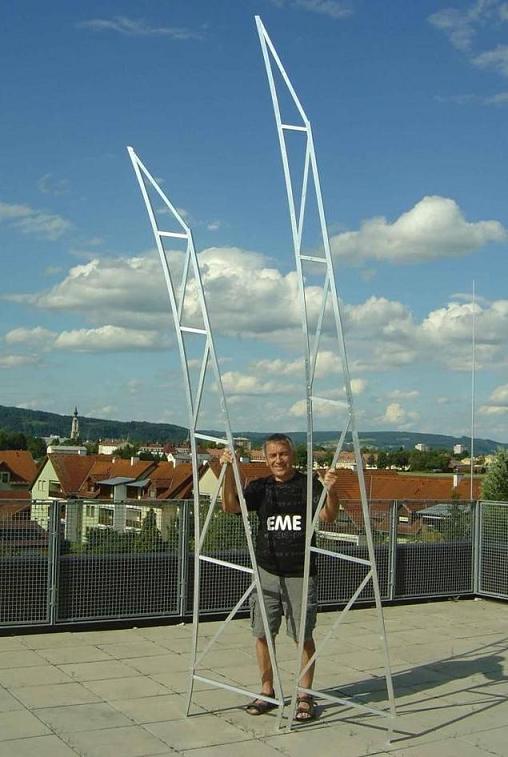
My dish has 36 ribs (18 full length, 18 half length), which means 19 different sizes and shapes. Of course, changing the rib template this often during building resulted in a lot of work.
But those extra hours finally accounted for less than 5% of the time I spent for realizing the whole project.
|
shortest and longest rib
|
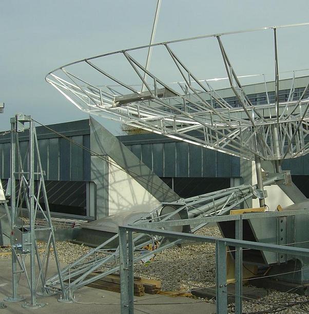
dish partly assembled
|
|
|
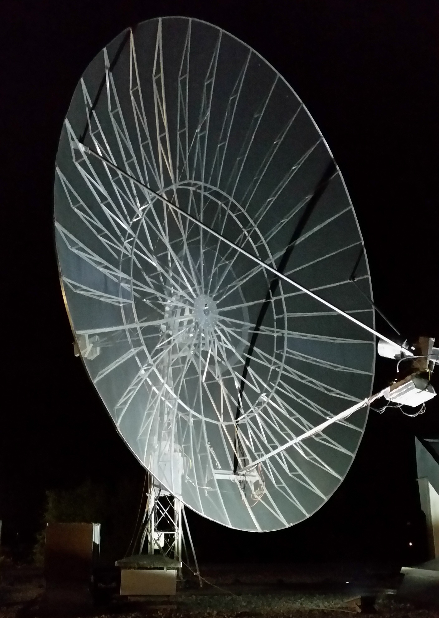
The tower construction has to be somewhat special as well
to allow the reflector to be tilted downwards. With a true offset dish it would have been 30 deg and the feed would have
been scratching the ground. For an easy access during assembling and (hopefully not necessary!) for repairs, it is a foldover construction. I can pull up the whole reflector on the mast by a cable winch. |
|
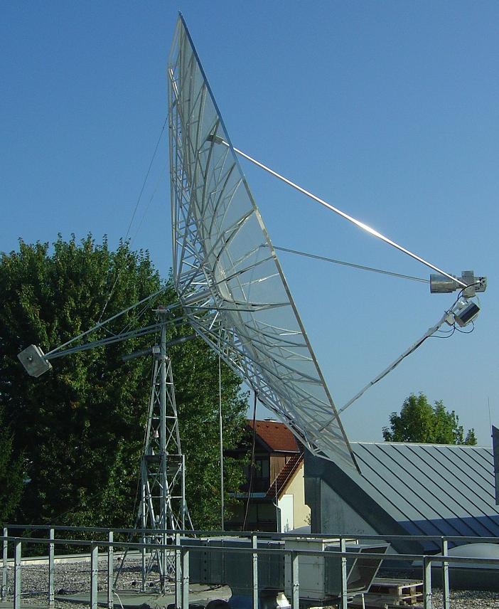
offset dish at 0 deg elevation (see the feed looking upwards 40 deg) I can reach the feed and sorrounding equipment standing on the ground
|
offset dish at 40 deg elevation (see the feed looking at the horizon) The SSPA is mounted directly underneath the RA3AQ feed
|
Finally after several years of planning and building I was ready to be QRV on 23cm
See (and listen to) some results at: signal plots audios and more
The dish is equipped with the same RA3AQ feed horn I used for
my former 5m prime focus dish. For the first measurements on 23cm I also had
the same preamplifier.
The 7.3m offset dish with a slightly lower f/D has 3dB more gain compared to
the 5m prime focus dish.
Sun noise has been 15.5 dB with the 5m dish at SFI 65. With the 7.3m dish I
got 21.5dB at SFI 104. Considering 3dB more gain and 2dB more SFI sun noise
should have been 20.5dB, so I received 1dB more than with a prime focus dish.
This is a quite good coincidence, which I had estimated before based on less
ground noise.
 |
 |
The equipment beside the antenna consists of a FT817ND transceiver, Kuhne transverter 28MHz to 1296 MHz, LDMOS driver stage and PA (2x PE1RKI) up at the antenna.
I use a PC with the usual software and additionally for remote controlling all the equipment. Some pictures are at OE5JFL station
For controlling the antenna I use a stand-alone ( without PC ) microcontroller based system of own design.
For more information : antenna control system