OmniTRACS RF/Synthesizer Board Conversion


Overview

The controller box for the Qualcomm OmniTRACS fleet tracking units includes a very nice RF/synthesizer board.  With some minor modifications, the oscillator on this board is capable of being tuned from 750 MHz to a little over 1,100 MHz.  This board is also the same one the San Diego Microwave Group uses for the 1152 MHz local oscillator (referred to as the "1152" synthesizer board) in their amateur radio transverter projects.  The initial work on converting these RF/synthesizer boards to different frequencies was originally done by Kerry Banke, N6IZW.  For additional information on this project, you should first review his work and notes which are available at: www.ham-radio.com/sbms/sd/rfsyn01a.htm

In this example, we'll be converting our RF/synthesizer board (1DN14ASSY-6475) to operate at 1,000 MHz.  To do this, you'll need to slighty alter some of the pins on the board's stock Qualcomm Q3216 (or Q3236 or Q3036) PLL synthesizer chip.  You'll also need to remove (or bypass) the board's HP IAM-81008 active upconverter mixer chip, which is marked "M810" and labeled "U19" on the PC board.  In order to increase the oscillator's RF power output, you may wish to "jumper" the upconverter's post-IF stripline filtering.  Stock, the board's MMIC amplifier (labeled "U21") put out around +3 dBm at 1,000 MHz with all the stripline filters intact.  Jumpered over on the MMIC's input, it'll put out around +12 dBm.  In order to active this MMIC amplifier, you'll need to ground one end of 1 kohm resistor "R62."

To set the frequency in the Qualcomm Q3216 PLL chip, you'll need to ground (logic 'low') or cut (logic 'high') certain pins which program the chip.  The stock Q3216 was programmed remotely via a serial string.  You'll need to disable this mode in the Q3216 and enable the "parallel" programming mode.  You'll want to use a fine-point side-cutters (or X-acto knife) to get at the individual pins on the Q3216.

The RF/synthesizer board has a 10 MHz Temperature Compensated Crystal Oscillator (TCXO) which is used to generate the reference frequency for the Q3216.  This is the same TCXO oscillator covered in GBPPR 'Zine, Issue #72.  You can "zero beat" the oscillator's output to WWV in order to tweak your reference to within a few Hertz of 10 MHz.

To power the RF/synthesizer board, it will require +15 VDC (or +12 VDC) at around 100 mA and +5 VDC at around 400 mA.  This is applied via the 11-pin "J2" connector along the edge of the board.

To make the board's VCO operate above 990 MHz, you'll need to add a surface-mount 1,000 pF capacitor from the loop inductor near "Q23" to ground.  This will help to increase the frequency tuning range of the stock VCO circuit.  With a little more tweaking, the VCO can cover a frequeny up to around 1,300 MHz.

One drawback to parallel programming the Q3216 PLL is that you can only use a 4-bit (1-16) reference frequency divider.  What this basically means is that you are stuck with a 1 MHz (10 MHz / 10) tuning step.  To get a finer tuning step resolution, you'll need to program the PLL serially with a PIC or other microcontroller, and this is a little more difficult then the project discussed here.

The San Diego Microwave Group has some very nice Excel spreadsheets on their projects website (www.ham-radio.com/sbms/sd/projindx.htm) for determining the "M," "A," and "R" counters for the Q3216 PLL when modifying these synthesizer boards to other frequencies.  The Excel spreadsheets seem to work fine under OpenOffice.

Pictures & Construction Notes

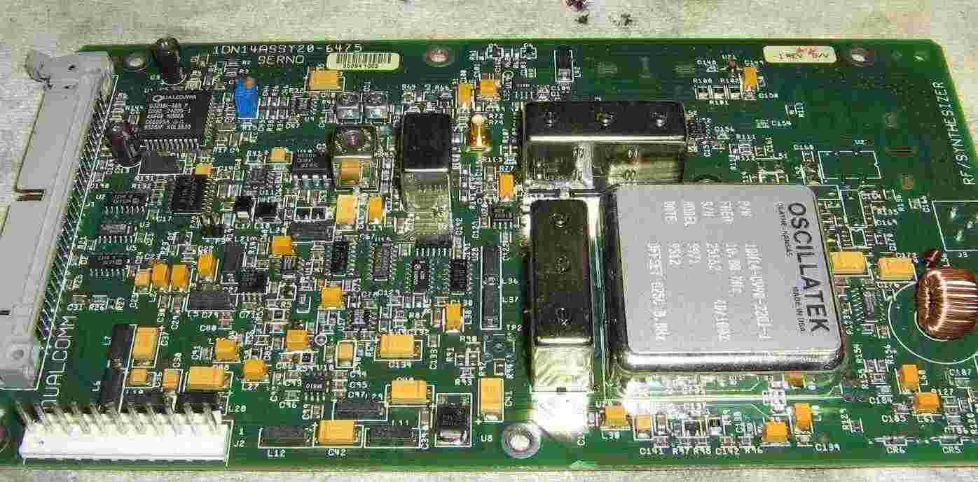
Overview of the stock Qualcomm OmniTRACS RF/synthesizer board (labeled 1DN14ASSY-6475).

The large silver box on the lower-right is the 10 MHz TCXO.

The 44-pin IC on the upper-left is the Qualcomm Q3216 PLL.

The "J2" power input connector is on the lower-left.

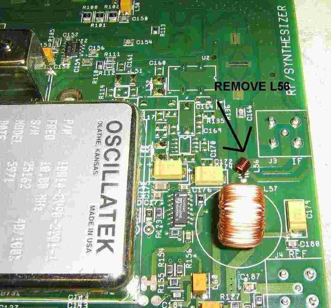
If you wish to use the board's onboard stripline filters, you should remove inductor "L56," which applies a +15 VDC bias to the RF output line.  This voltage is not needed here.

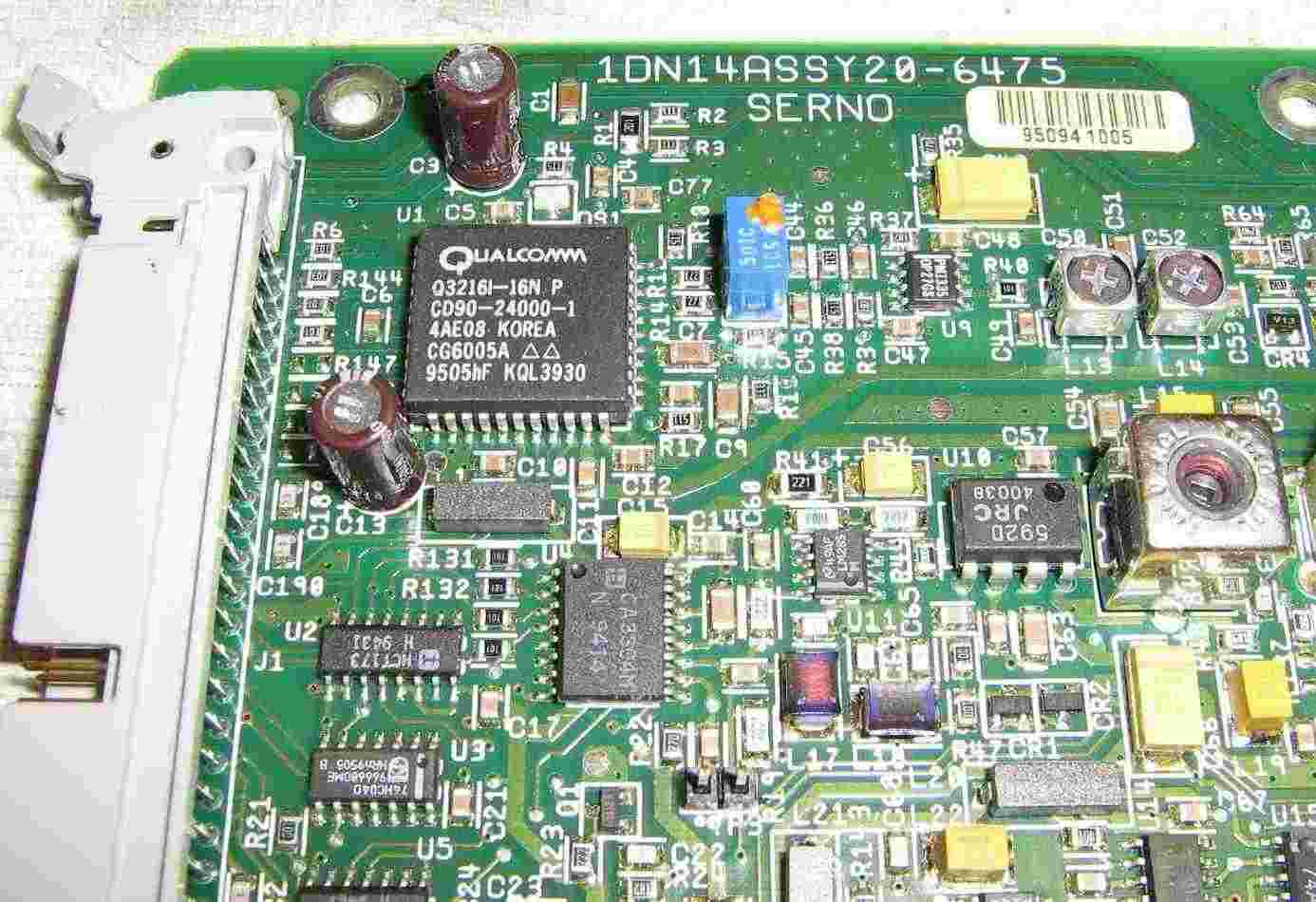
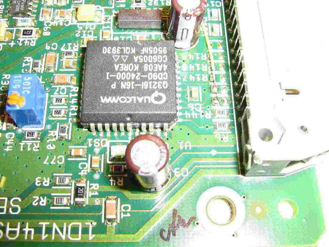
Overview of the Qualcomm Q3216 PLL and its supporting ICs.

IC "U2" (74HCT173) and "U4" (CA3304) will need to be removed.

These were originally used to control the PLL remotely, but you'll be enabling "parallel" programming mode which allows PLL divider programming by raising (logic 'high') or grounding (logic 'low') certain pins on the synthesizer.

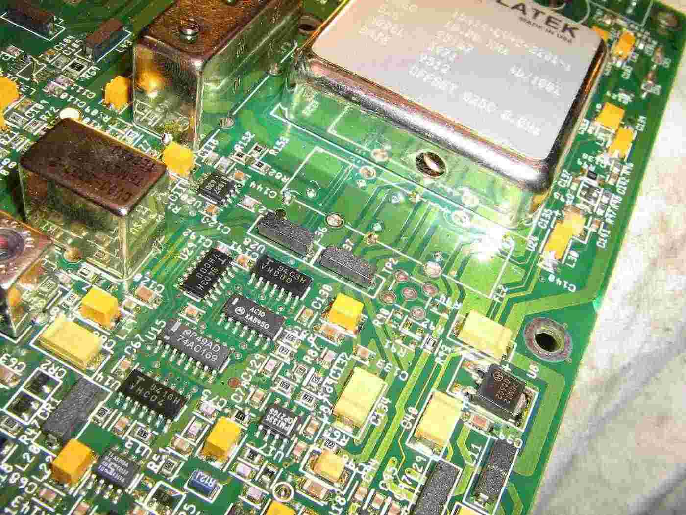
Overview of the RF output amplifier and upconverter mixer section.

The stripline filter on the MMIC's RF input (and output, if needed) will need to be jumpered over.

The upconverter mixer ("U19") will also need to be removed or bypassed.

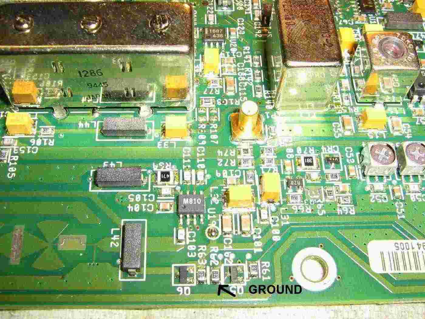
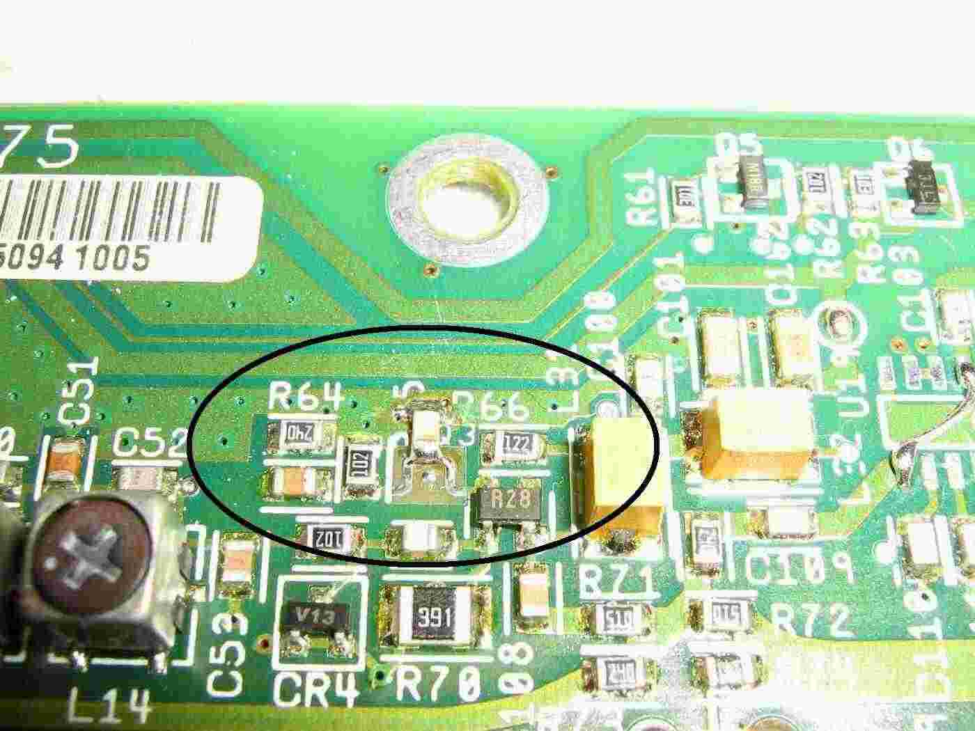
Closeup of the HP IAM-81008 active mixer ("U19") section.

To enable DC power to the MMIC RF amplifier ("U21") on the mixer's output, ground the end of "R62" nearest the board edge.

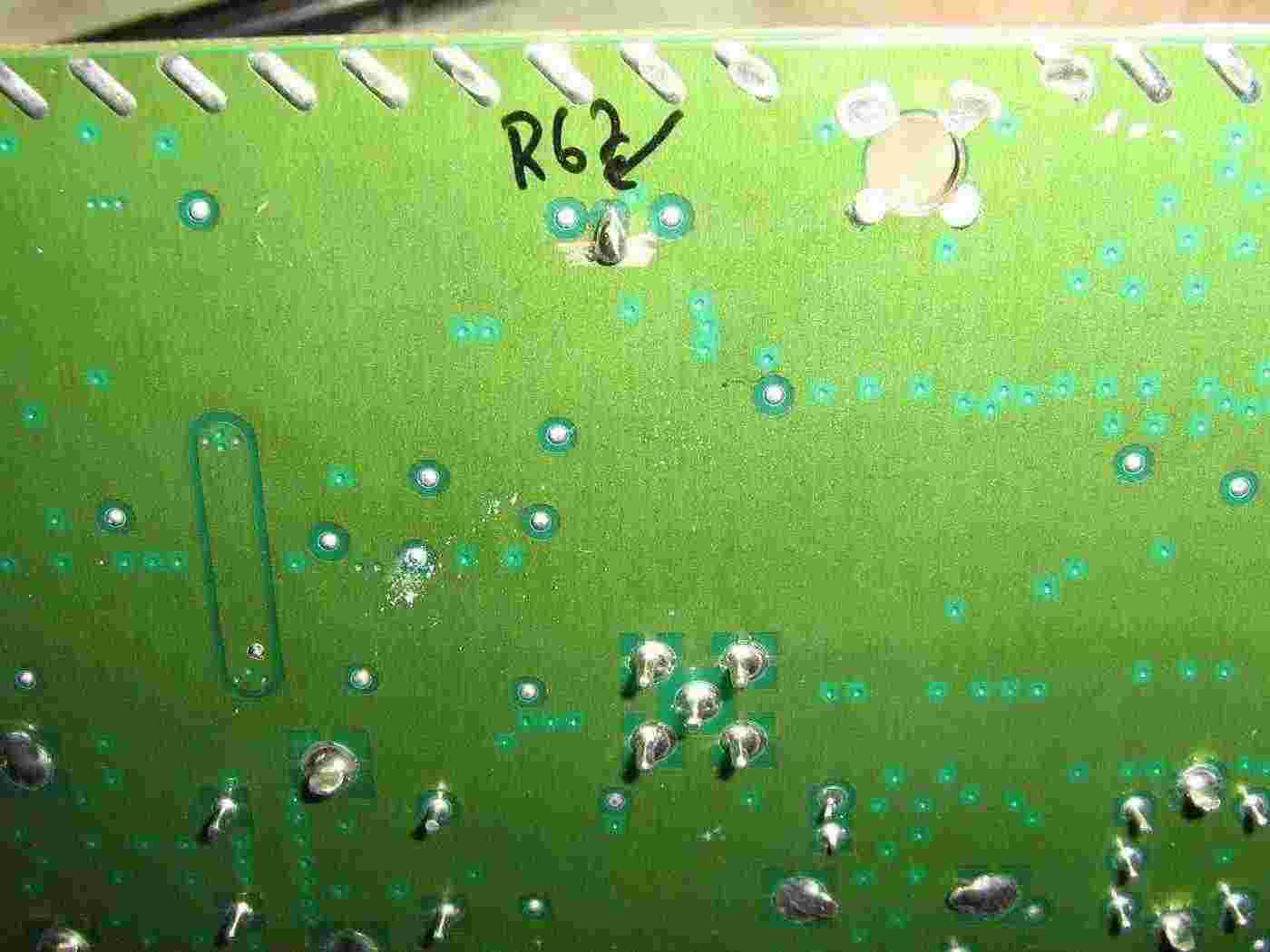
Ground the end of "R62."

You can do this on the bottom-side of the board by "ohming" out the proper solder vias and making a "solder blob" jumper to ground.

In order to access the frequency-tweaking trimmer capacitor for the 10 MHz TCXO clock oscillator, you'll need to remove filter "FL2."  This is optional, but useful.

Remove "FL2" by cutting the exposed pins and rocking it back-and-forth with a Vise-Grips.

Modifying pins on the "U1" Q3216 PLL.

The yellow wire along the right-edge goes to ground.

To tune this board to 1,000 MHz, you'll need to do the following to the Q3216 PLL.

Set the "M" counter to 1000.

Set the "A" counter to 0.

Set the "R" counter to 10.

To do this:


1.  Short pin 16 to 17.          This enables on the on-chip prescaler.

2.  Cut pin 22.                  This enables parallel programming mode.

3.  Ground pins 13, 10, and 9.   This sets the "M" counter to 1000.

4.  Cut pins 5 and 2.            This sets the "R" counter to 10.

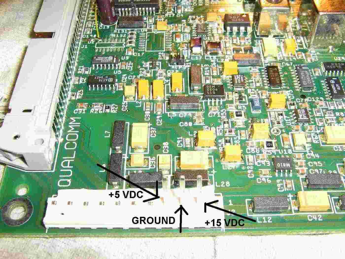
Powering the RF/synthesizer board.

Apply +15 VDC to pin 2 of "J2."

Apply +5 VDC to pin 4 of "J2."

Pin 3 of "J2" will be ground.

You can power the board with a regulated source of +12 VDC if you apply the voltage to the output pin of the synthesizer's board 78M12 regulator.

To allow the oscillator to cover above 990 MHz, you'll need to add a SMT 1,000 pF capacitor from the inductor loop near "Q23" to ground.

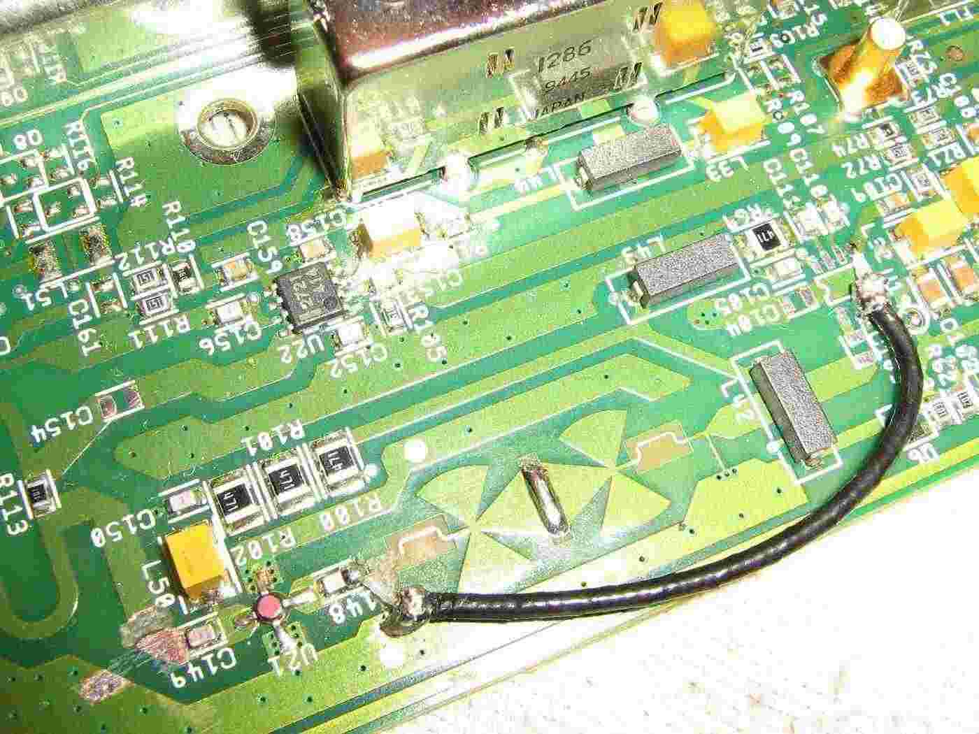
To access the RF output of the VCO, you'll need to remove the upconverter mixer "U19" and run a small piece of coax from pin 5 on the "U19" pad to the RF input of "U21."

Pins 2 and 3 on "U19" can be used as ground.

Note the cut traces near "C149" and "C148" to isolate the input and output of the MMIC RF amplifier.

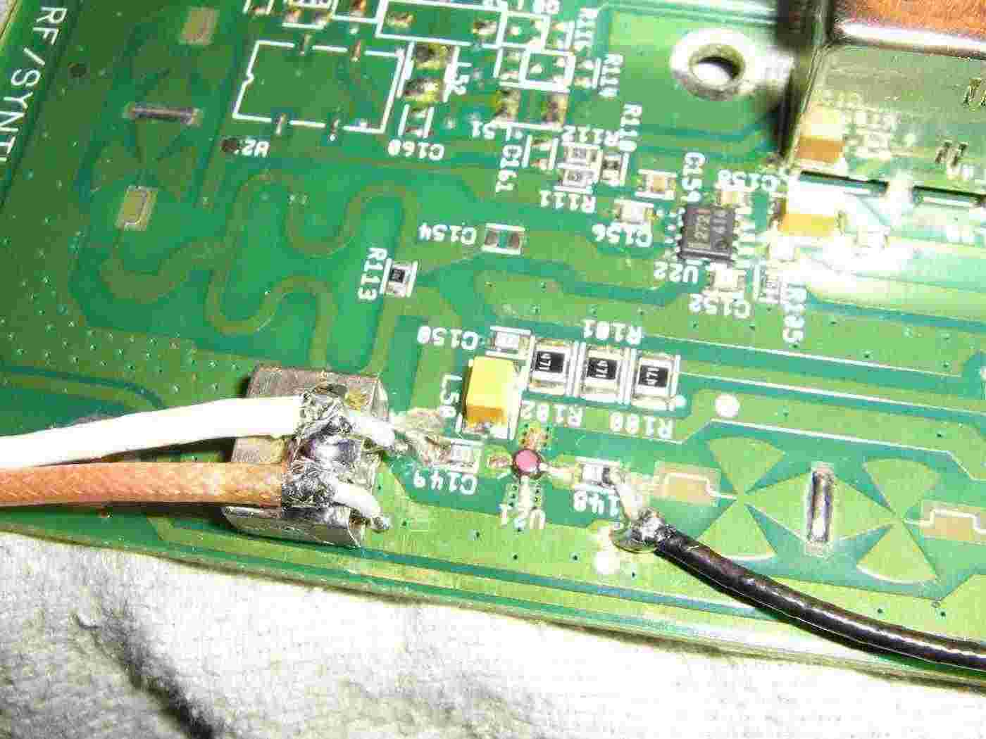
Running the RF output of "U21" into the local oscillator port of a Mini-Circuits TFM-150 mixer.

This application was for a 1-2 GHz receive converter for extending the range of a spectrum analyzer.

On the TFM-150, pin 1 is for LO input, 1,000 MHz in this case.

Pin 2 is for DC-1,000 MHz IF output.

Pin 4 is for 1,000 to 2,000 MHz RF input.

Pin 3 and the mixer's case is ground.

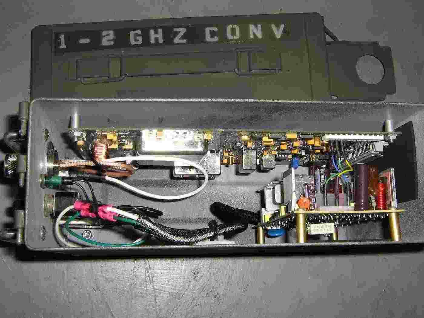
Internal overview of the 1-2 GHz receive converter.

The RF/synthesizer board is is powered from a little switching power supply.

The 1-2 GHz RF input is via the panel-mount N connector.

The DC-1 GHz IF output is via the panel-mount BNC connector.