
|
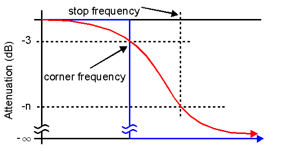
In the stylized graph above, the ideal low pass response shown in blue. This displays zero attenuation at frequencies from zero to our corner frequency and infinite attenuation at frequencies above that. The graph in red shows what the Butterworth filter can accomplish. In the filter that can be accomplished with lumped inductors and capacitors, the pass band allows up to three decibels of attenuation. |
At some higher frequency, specify a desired attenuation, n, in decibels. Make the slope of the graph between the 3 dB and the n dB points steeper by making the difference between the corner and stop frequencies smaller. Choose these frequencies wisely to design a filter that performs well in the current application. |
|
First, determine a "corner frequency" which is a frequency that has an attenuation of 3 dB on it's downward slope. For instance, there might be some interference on the broadcast band radio. there needs to be a limit on the input above 1800 kHz. This is the corner frequency. At 2200 kHz the attenuation must be about 30 dB. That makes 2200 kHz the stop frequency and the attenuation is 30. Type 1800 kHz in the top box, labeled "Corner Frequency (Hz)" in a number of different fashions, using only the allowed characters 0-9, E (upper case is automatic), and . (a decimal point.) All of the following are legal: 1800000, 1.8E6, 1800E3. This is not allowed: 1800 kHz. Following the same formatting, enter 2200 kHz in the second box labeled "Stop Frequency (Hz)." And then in the third box enter 30, that's the box labeled "Attenuation (dB)" In the fifth box, labeled "In/Out Resistance (Ohms)," enter the resistance in Ohms of the source and load which is 50. |
Click the "Computer Calculation" button in the green "Order" box. The computer will calculate the order and display it in the fourth box labeled "Order." Make an evaluation of the order number. It is possible that 18 (this example) was more than the number of capacitors and coils desired. Examine the criterion a second time. Perhaps less attenuation or a higher stop frequency could be used without suffering too much interference. For the moment, assume an order of 18 is acceptable. Click either the button labeled "Tee - Series" for an inductor input filter, or "Pi - Shunt" for a capacitor input filter. See the "Help - Geometry" for more information. After that button is clicked, the calculations are made. Depending on how the configuration is set up, the results may be shown immediately or use the "File - Retrieve" menu item to launch the text editor to see the results, or compute other filters. Later launch the text editor to see the files or open the Butterworth filter folder and double click the files to view the data after exiting the Butterworth Calculator. |
|
Consider a fifth order low pass filter with a corner frequency at 500 kHz and input-output termination resistances of 50 Ohms. Past experience guides these decisions. Type 500 kHz in the top box, labeled "Corner Frequency (Hz)" in a number of different fashions, using only the allowed characters 0-9, E (upper case is automatic), and . (a decimal point.) All of the following are legal: 500000, 5E5, 500E3. "500 kHz" is not legal. Type a "5" in the fourth box labeled "Order." Type 50 in fifth box labeled "In/Out Resistance (Ohms)." In the green "Order" panel, click the "Manual Entry" button. |
The corner frequency and the order are now locked in. Click either the button labeled "Tee - Series" for an inductive input filter, or "Pi - Shunt" for a capacitor input filter. See the "Help - Geometry" for more information. See Example One for how to view the computed data or retrieve the saved data files. |
|
If the filter has a corner frequency in the range of 50 kHz to 75 kHz, consider an active filter. The low cost of top quality operational amplifiers and the associated resistors and capacitors make the active filter an attractive option. This is emphasized by the fact that inductors for these frequencies inductors tend to be bulky and expensive. Be aware that amplifier gain-bandwidth considerations will limit the upper frequencies passed by the active filter. |
If the filter has a corner frequency above about 500 MHz, consider other techniques entirely. The small electrical size of the lumped elements make stray capacitances and inductances an important part of the physical layout possibly detuning the entire circuit. The Buuterworth Calculator is limited to frequencies less than 1E10 Hz. |


