
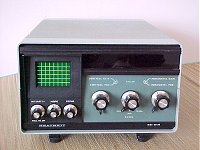
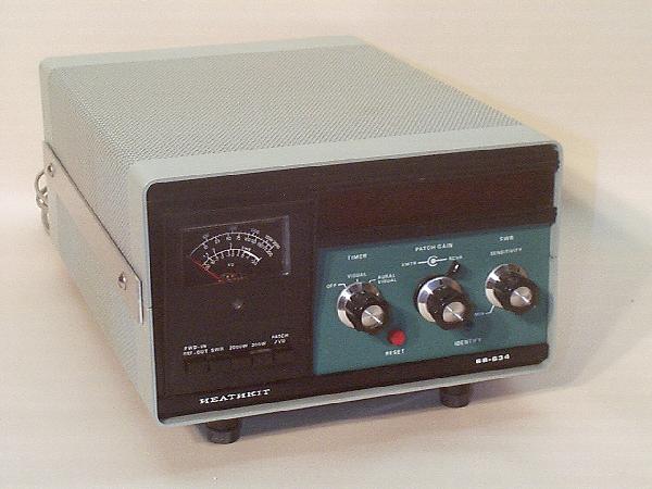
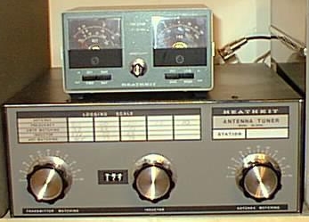
News!My "Boat Anchor" collection gets started (Yep, I've got yet another bug). I have three pieces coming next week - HeathKit SB-614 Station Monitor with scope, SB-634 Station Console (includes clock, timer, Phone Patch, SWR and Watt meter), and SA-2040 (Tuner - 3.5-30 Mhz 2KW PEP/1KW CW). These pictures are not of the actual pieces that I have coming, but pictures I found on the internet. (The SA-2040 tuner doesn't have the meters.) |
   |
|
SB-614 SB-634 SA-2040 |
My "Shack's" operational area |
|
|
|
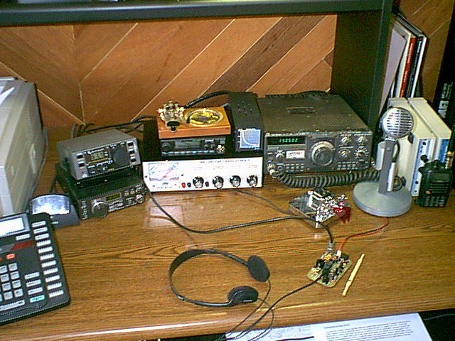
A portion of my desk where I operate my radios
from. At the far left, just above and to the right of my telephone
is my new Elecraft K1 radio, which despite it's small size has become my
main "rig". It is sitting on top of a remote VFO for my
Kenwood TS-130s, which is sitting to the right, just to the left of the
microphone. Immediately to the right of the K1 and VFO is an MFJ
antenna tuner (the light colored panel), and sitting on top of that is a
Alinco DR-1200 data-only 2-meter radio, one of my straight keys (it also
doubles as a coaster!), and a
"Dummy Load". To the right of those is my Kenwood
TS-130s, an HF CW and SSB radio. The TS-130s was actually my
mother's first radio, and it has done quite a bit of traveling and seen
some wild adventures and mis-adventures, including Hurricane Hugo in 1989 in the Caribbean.
Just in front of the TS-130s is my MFJ iambic paddles that I'm using for
CW. The microphone over to the right is a Shure Brothers
Model 440 on a Electro-Voice 423A stand that I picked up for $5.00 at a ham fest a few years
ago. I'm not certain about the stand, but the Sure Bros. 440
microphone was manufactured during the 1960's (the model was
discontinued in 1970). That $5.00 dollars has gotten me quite a few "Nice
Audio" comments from other hams that I've spoken with on the
air. Much better than the hand-held I almost forgot - at the front right of the desk, to
the right of the headphones, is the For Antenna's, at the homestead I have an old Butternut HF9V-X vertical up on the roof (see drawing to the right). This antenna covers 80, 40, 30, 20, 15 and 10 meters. Bencher - the company known for their iambic paddles, among other things - purchased Butternut, and stopped production on a few of the antennas. The HF9V-X production stopped in 1997. The -X suffix meant that the antenna was manufactured to break down into shorter pieces so that it would be UPS Ship-able. Unfortunately, that also meant that the 17 and 12 meter bands were sacrificed. For portable operation, I have a MFJ-1910 telescoping portable mast (see picture at left), a DK9SQ vertical-loop antenna for 40 thru 10 meters, and am also experimenting with antennas. (Dk9SQ, Walter, also has a telescoping mast that is a bit lighter than MFJ's version, is a little more expensive, and is probably of higher quality).The MFJ mast is a telescoping fiber-glass mast that weighs only 3.3 lbs. and is only 3.8 feet collapsed, but extends to a full 33 feet when fully extended. I set up the mast and antenna the other day - pictures of it set up are on my "Images" page. My last experimental antenna was made strictly with speaker wire. I took about 60 feet of speaker wire, split the two joined wires at one end, making the two halves of a dipole for 20 meters. At the center of the dipole, rather than using a center insulator, I tied an electrician's knot so that the speaker wire would not split any further. The rest of the speaker wire was left together, making a balanced feed line. I don't know what the actual impedance of the feed line is, but using a 4:1 balun at the radio end, the tuner in my K1 was able to get the antenna tuned up to about a 1.2 SWR. I put the antenna up in my back yard as an inverted V using the telescoping mast as the center support. I made a few contacts, and got reasonable signal reports. Not the ideal antenna, but compact and usable in a pinch. I'll have to borrow an antenna analyzer to see just how efficient (inefficient?) the speaker wire-balanced feedline-dipole is. When I get around to doing that, I'll put the results here. |
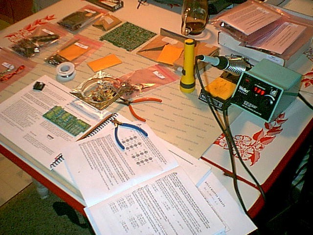
"Bench", or Building Area |
 |
|
This is where I do the building and repairs. This is where I have the most fun, and experience the most frustrations of this hobby of mine. I'm learning quite a bit, but still have a LONG way to go. You can't see it in this picture, but one of the most important tools for me was a lamp/magnifying glass that Linda picked up for me. It's one of those that clamps on to the side of the table, and stretches out and stays where you put it. I don't have the eagle eyes I did when I was a bit younger, so using the 'glass' to look at the tiny print on some of the parts has saved me from a few mistakes. At times I've used it while soldering also. This picture was taken during the first stage of building the K1 radio. Although I tried, the table certainly didn't stay this organized! Shortly after this picture was taken, another bench tool arrived that has proven invaluable for my fumble-fingers - a PanaVise circuit board holder. I know that some builders don't like to use circuit board holders, but I think it helped me a great deal. |
Click here to see a copy of my QSL card.
 FOXX-3 20-meter transceiver that I recently built.
Here I have it connected to power and to my antenna, and have been
trying to make some contacts with it.
FOXX-3 20-meter transceiver that I recently built.
Here I have it connected to power and to my antenna, and have been
trying to make some contacts with it.