|
Gotta Match? Way back When, when I was a new, young Ham, I was eager to work all the HF I could. Problem was, I had limited usable antenna space. I priced a Transmatch and found them to be beyond my meager means. Well as a new, young Ham, I scrounged everywhere and had put together a respectable Junque Box... it filled the garage. I looked through my treasure and found a couple of dandy high power air variable capacitors and a roller inductor with a turns counter. I had also acquired a transportable rackmount cabinet with chassis. To me this looked like the perfect Transmatch. I built it as an Ultimate Transmatch, and it tuned my 80m Dipole to any frequency I chose. I built it, I used it, I loved it, and I lost it. Somehow it didn't make the trip in a move. I hope whoever found it can appreciate its beauty. After that move, work didn't permit a lot of time for HF operations so HF fell by the wayside. Now, years later, the HF bug has bitten again, and again I have limited usable antenna space. After many moves and years of maturity, my junque box no longer fills a garage, but I did find the makings of another transmatch; not as nice as my first beauty, but workable. |
| Design: |
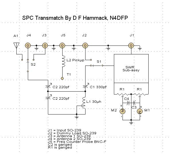
The Schematic was drawn with PCB123, A free program available at www.pcb123.com/
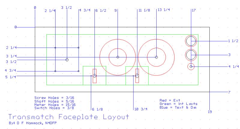

The Layouts were drawn with Cadvance 6.5b, a free program available at www.cadvance.com
| Construction: The chassis is a 19" rackmount unit with a 7" faceplate and is 11" deep. This is plenty of room to avoid stray capacitances and other unwanted interactions, even if I later decide to upgrade the capacitors. The unit is surplus and is already punched for all rear panel terminals. In fact, I will need to make a cover plate to hide some unused openings. Since I do not have a feedthru insulator for the end fed wire, I will be using 2 pieces of 1/4" Teflon to fashion a feedthru insulator. Mounting of the roller inductor is pretty straight forward. As the capacitors are energized on both the rotor and stator, they must be insulated. Ideally, ceramic isolation standoffs would be used, but those were not to be found in my junque box. However I seem to have great quantities of 1/4" Lexan. I cut a square to use as an isolation platform and some 1/2" PVC pipe to make standoff spacers. C1 is mounted to the platform with the required 6-32 hardware and Lexan spacers to raise the shaft to the same height as C2. C2, a triple ganged 220pf, is usable, but is quite old and shows neglect before I got it. It is a little rusty and there was some oxidation on the plates. Also. the mounting hardware was riveted standoffs. They were rusted beyond use, and were mounted on the wrong axis to suit me anyway. My mounting solution for C2 consisted of drilling 4 pairs of holes and using nylon wire ties to secure it to the platform. I was pleased this made a very snug mounting. I don't have any insulating shaft couplings, so I am going to try using phenolic or Lexan shafts and coupling them to the capacitors with 1/4"ID neoprene tubing and small hose clamps. Very little effort is required to turn them, so this should work. L2 is nothing more than a short piece of random length #12 solid wire soldered to J5. It is just a pickup to sniff out enough RF for my frequency counter to count. I cheated on the SWR metering. I had an old meter with one of the panel meters broken out. I had been meaning to fix it , but never got around to it. Since I had a couple of really slick little mil-spec micro-ammeters, I decided to install the remains of the old meter, whole into the transmatch. The calibration pot and meter leads will be run to the faceplate while the rest of the circuitry remains in the old enclosure, isolated from stray RF. I am presently working on the construction. Since I must work outside the going is slow due to rain. I have the faceplate all drilled and ready, but since I did not have a step bit to drill the meter holes, I had to use a rotary file. The drill got away from me a couple of times so I now have some nicks on the faceplate. Though I had not planned on painting it, it looks like it will be necessary now. Oh well, Flat Black will match my rigs better than Engineers Gray anyway. |
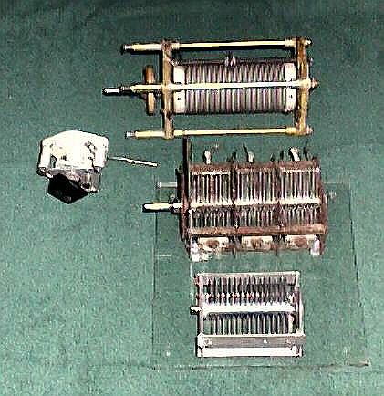
These parts are the heart of my new transmatch. The capacitors have a 0.075" plate spacing. This should be adequate even for my Drake TR-4C when I get it restored.
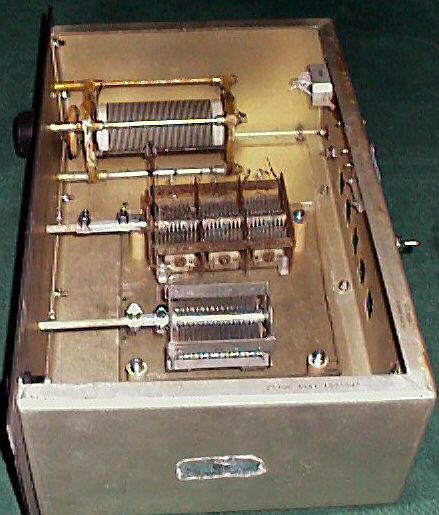
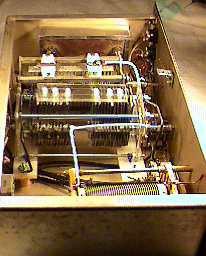
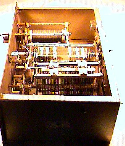
This is the inside layout. It isn't wired yet, but should be done soon. The isolation platform is 11/2" above the deck. Note the shaft couplings. As I thought, 1/4"ID tubing was perfect as a coupler. I live in a small town, so when I went to look for non-conductive shaft material, I found nothing.... except, that is, 1/4" dowel stock. Maple is a pretty good insulator if you keep it dry. |

This shows the mounting technique I used for the capacitors. Note, too, the rust on the ganged capacitor. I will almost certainly replace this in the future
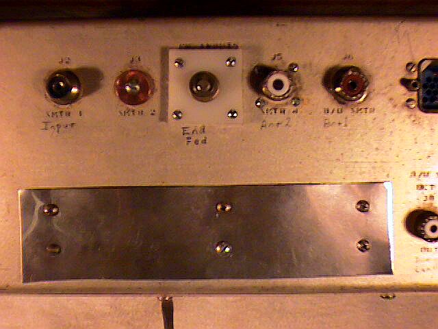
The top picture is pretty much how it will look when completed. I do not have a turns counter. Someone like to volunteer one? The bottom image is of the back panel. From Left to right, the connections are: input, ground, vacant, end fed wire, antenna 2, antenna 1, down to lower right- dummy load, and the frequency counter probe. The blue connector in the upper right corner is a remnant of the original application - it is not used. The row of square openings at the bottom was for 5 relays. I hated to leave openings, but the relay sockets wiring made quite a birds nest. |
|
4/01/03 The final update on my Transmatch Project. I have been working on this project off and on for about 3 weeks. As I assembled it, I had less and less confidence in my capacitors, particularly the ganged capacitor. I got it completely assembled and was about to start the wiring when I gave up on them. I had a very nice Hammerlund 450pf transmitting air variable, but could find nothing to use for the ganged capacitor. I was looking over the Web and found an article by DL5DBM, Anwar von Sroka, on building your own capacitors. I took a great interest in the article and started making plans to build my own. My method differed a little from Anwar's but it was very effective. I bought all materials except the Lexan for about $15.00 at my local, small town hardware store, and used common, household tools. Check out my method of construction here. |
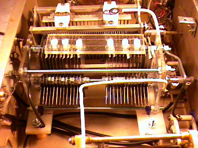
This is an internal view from the left side of the unit. In the foreground you can see my homebrewed capacitor.
This is a detail image of the homebrewed capacitor
This is the Connector Panel
Detail of the Connector Panel |
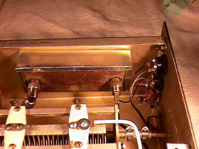
This is an internal view from the right. Since I did not have any copper ribbon or braid, I used #10 solid copper wire for wiring. Also, I had no RG/8 so instead I have it wired with RG/58 for the time being.
This is a detail image of the SWR metering circuitry
And the Face Plate (Alas, still no turns counter for the Roller Inductor)
Detail of the SWR Meter (Same circuit as a Swan SWR-1) |
| This wraps up my Transmatch. I hooked it up to my 80m Inverted Vee and tuned up on 80m, 40m, and 20m. I therefore doubt I'll have trouble on any other bands. I tested it on my Patcomm PC-500 and it worked well at 15 watts. I hooked it up to my Swan 100MX and that worked well, too. I don't expect it would take full legal limit due to the materials used in my homebrewed capacitor, but it will handle any barefoot rig, and probably up to a kilowatt. It still isn't quite as nice as the one I lost, but I think I will be quite happy with it. |
Copyright 2003 David Hammack, A.R.S. N4DFP