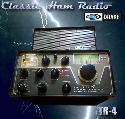
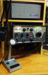
To the right is pictured my Drake TR-4 and MS-4 Speaker. The AC3 power supply is housed inside the speaker cabinet. I found this combo at the 2005 hamfest in Timmonium, MD. I got it for $130. I found it sitting on a table amongst some other items (non ham stuff). It appeared to be in decent shape so I asked how much the fellow wanted for it and if it worked. The asking price was $150. He couldn't tell me much about the rig except for that it "lit up". It seems that he and his friend had gotten it with the intention of putting it on 11 meters. Much to their dismay they quickly found out it couldn't be used on the 11 meter band. Fortunately they didn't get inside the rig and butcher it! I made my monetary offer which he accepted without hesitation. I was now the proud owner of a TR-4! Unfortunately it didn't have a microphone but that was just a minor inconvenience.
Fast forward six years...
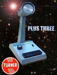
Well here we are six years later and finally I get a microphone for it! Actually in the past few years I didn't have much tome to play radio although I did power up the rig as much as I could mainly to keep the caps from drying out. Now that I had loads of time on my hands I put some effort into obtaining a mic and mic connector. A friend donated a Turner +3 desk mic to the cause, a mic connector was obtained from a hamfest, I did an alignment and the rig finally made its on air debut in July 0f 2011. About a week after its debut one of the filter caps in the AC3 power supply decided that it no longer wished to be a filter cap so a power supply repair was in order. The rig is an early version built in 1965 so a few hiccups are to be expected. I ended up rebuilding the supply and doing a couple of simple mods on the rig which are detailed below. The TR-4 is working beautifully now and is now my primary AM rig. I love this old rig!
|
|
Click image for larger view
|
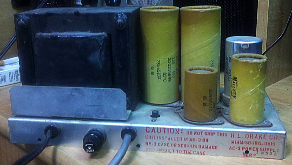
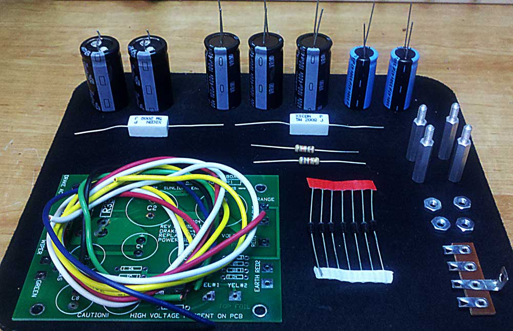
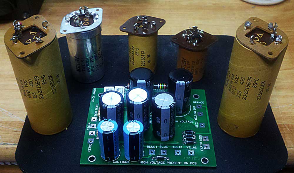
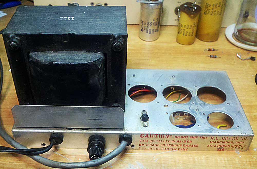
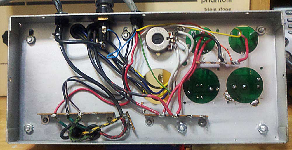
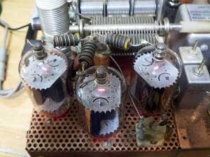
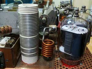
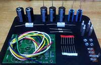
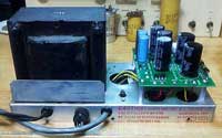
To the left is my AC3 power supply. The tall cap directly to the right of the transformer is the one that failed (open). This is just one of two caps in the section of the supply that provides the plate voltage to the three 6JB6s used in the finals of the rig. With the one cap open I was only getting 340 volts to the plates during transmit instead of 650 volts. I found a place online called N0JMY's Hayseed Hamfest that sells NEW, close to original caps for the AC3 (as well as other boatanchors). I was going to replace just the two caps (aproximately $25 each plus shipping) but that would have left three other forty five year old caps in the supply as well as the original diodes and resistors. While hunting down parts on the internet I discovered The Heathkit Shop. They offer a COMPLETE rebuild kit for the AC4 supply which is easily adapted to the AC3 for $65. The kit includes all new caps (new style, smaller), new diodes, resistors, PCB, mounting hardware, wire and instructions for installation in the AC4 supply. As I was not concerned with keeping the supply's original configuration I went for the complete rebuild kit and am pleased with the results. The AC3 and AC4 power supplies are virtually the same eletrically with the only real difference being the physical layout of the components. The Heathkit Shop also has power supply kits for other equipment and a few other goodies as well.
|
|
THIS EQUIPMENT CONTAINS HIGH VOLTAGE THAT CAN SERIOUSLY INJURE OR KILL YOU! PLEASE WORK SAFELY!
|
|
TR-4 "printed" material...
PDF Files
|
|
The AC3 Rebuild... Click on any image for a larger view |
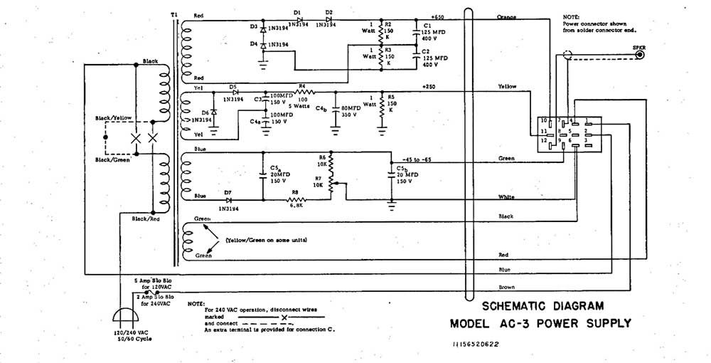
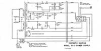
Original Wiring Diagram
|
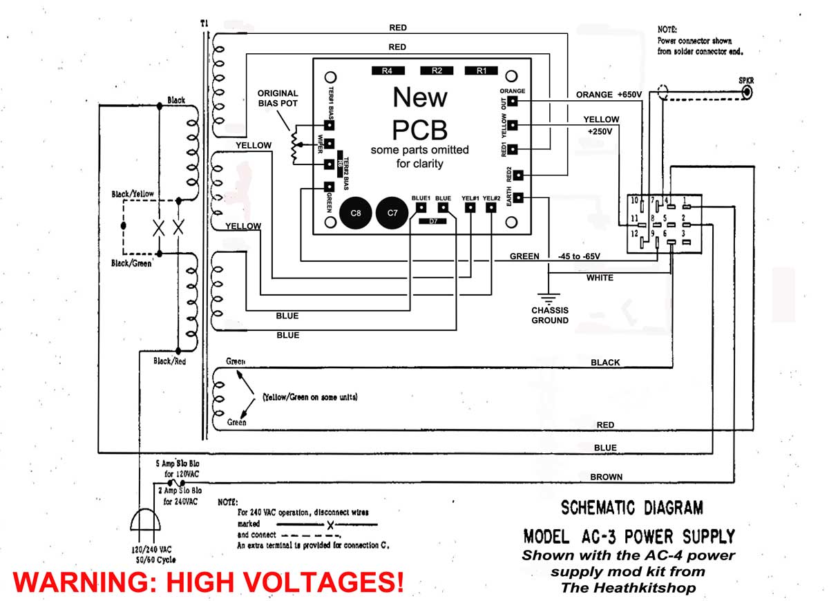
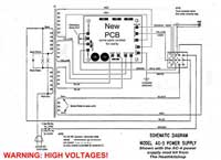
New Wiring Diagram
|
Unassembled Kit
|
New vs Old
|
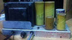
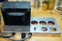
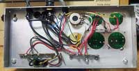
Stripped AC3
|
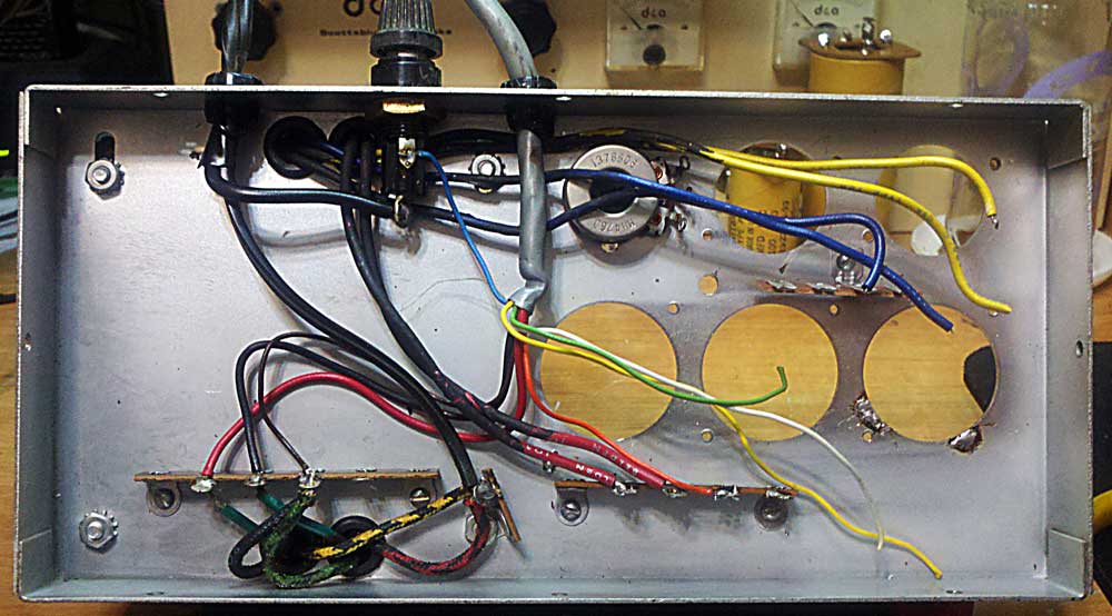
Underside Stripped
|
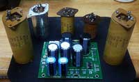
Complete!
|
Underside Completed!
|
There three 150K ohm resistors used in the AC3 supply. Just for kicks I decided to measure the old resistors that were removed. They measured as follows: 190K. 225K and 384K ohms. Some things DON'T get better with age!
|
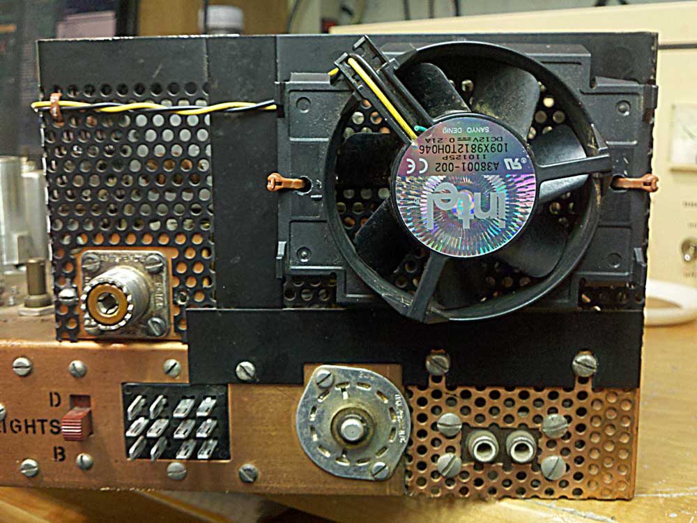
Keeping your cool... a fan for the TR-4 |
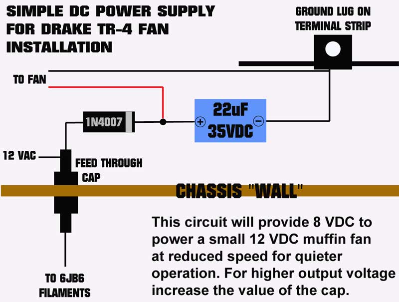
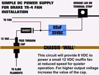
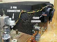
This is an easy way to install a fan on your TR-4 with only a few components and a little wire. Using the existing holes in the chassis and wire ties you don't even need to drill holes! You'll need a 1N4007 diode, an electolytic capacitor (anything between 10 and 100uf, higher value = higher voltage to fan), a 12 VDC fan, some wire, a little heat shrink tubing and a 2 pin connector (optional). Should it blow in or out? There seems to be two schools of thought on this one. I figure in or out, any air movement is a good thing! Due to the configuration of the fan I used mine blows in.
|
Fan power supply circuit. 12 VAC from the 12 V filament supply is the source
|
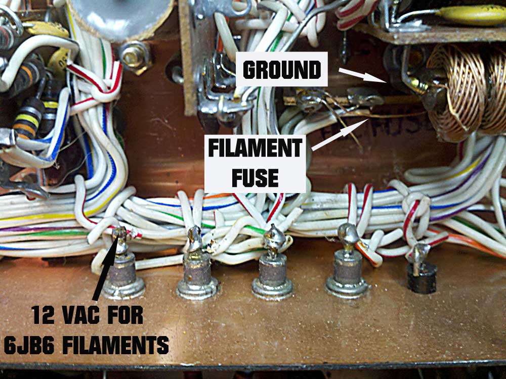
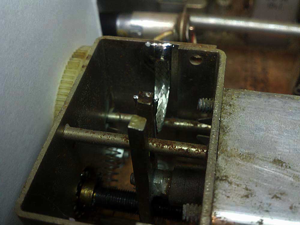
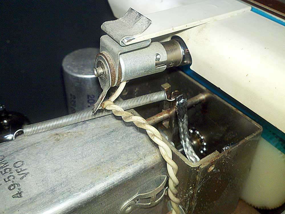
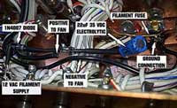
Convenient place to pick off the 12 VAC. This is at the outside of the "wall" that separates the RF output compartment from the rest of the rig.

|
All the required components and wiring installed
|
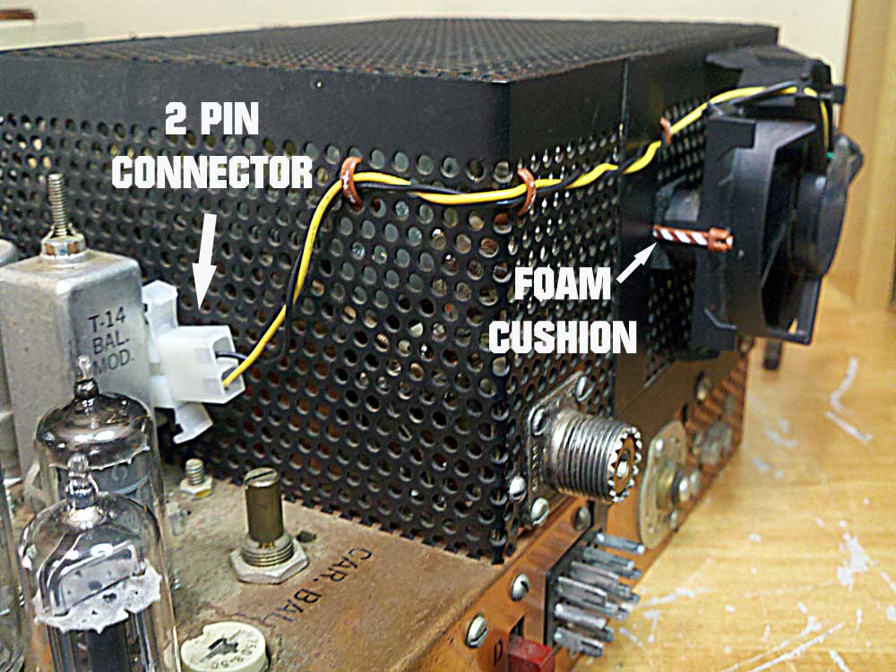
The fan and wiring installed on the RF output cage
|
| |
|
|
|
|
|