The best performing receive antenna tested was an active loop design by John (G8CQX) upon which my receiving antenna is based. I was particularly impressed by the stability of Johns amplifier design regardless of the construction methods used. Initial daytime tests with a 1 Metre diameter loop proved the loops ability to receive signals over several octaves and with much reduced local QRM levels. However, tests after dark revealed overloading of the loop amplifier from powerful SW broadcast stations. The cure for the signal overloading was to increase the standing current in the loop amplifier devices taking care not to exceed the safe collector power dissipation. The resulting modified loop amplifier no longer overloads even with an increased loop diameter of 1.5 Metres or more. The loop diameter of 1.5 Metres was found to be optimal at my QTH. The active loop antenna has now been thoroughly evaluated over a two and a half year period with very pleasing results. A nice feature of the broad bandwidth loop is that no re-tuning or adjustments are required to the antenna when changing bands.
Circuit details and constructional notes.
Minor
modifications have been made to John’s original design to protect the loop
amplifier when used in conjunction with a transmitter and to improve the strong
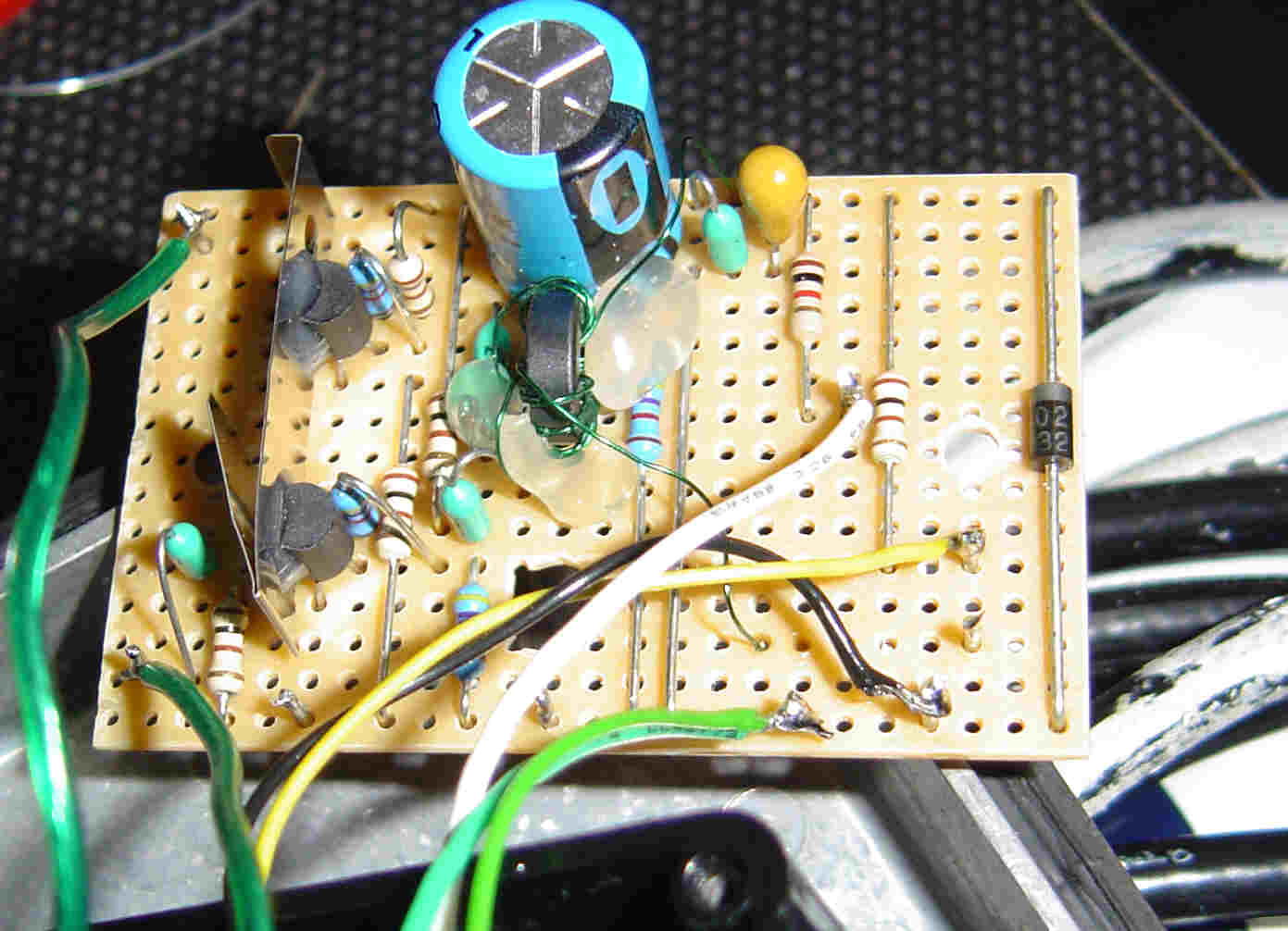
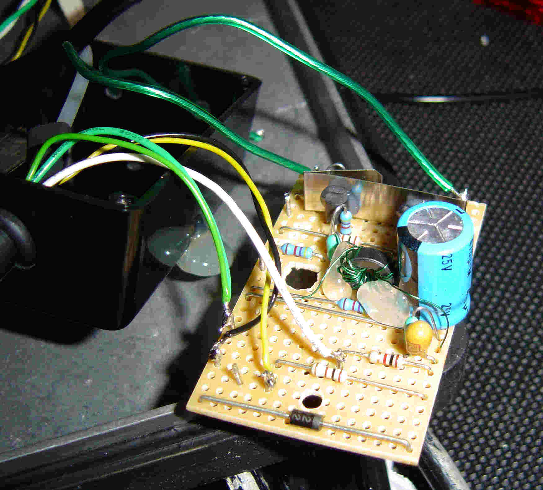
signal handling capability. The construction of the amplifier does not appear
to be very critical and four versions have been successfully built using
various methods of construction. The first used breadboard construction, the
second and third built over a ground plane while the current version is built on
a scrap of strip board. I have successfully used various devices including
2N2222, 2N3866 and BC337’s. The current version is fitted with a pair of
unmatched BC337’s and has been in regular use for over two years. BC337 devices
have been used simply because I have a good stock of these in the junk box.
Both of the transistors run with 30 mA of collector current requiring a small
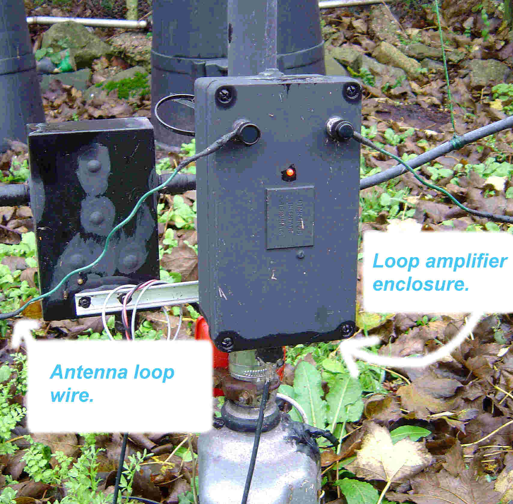
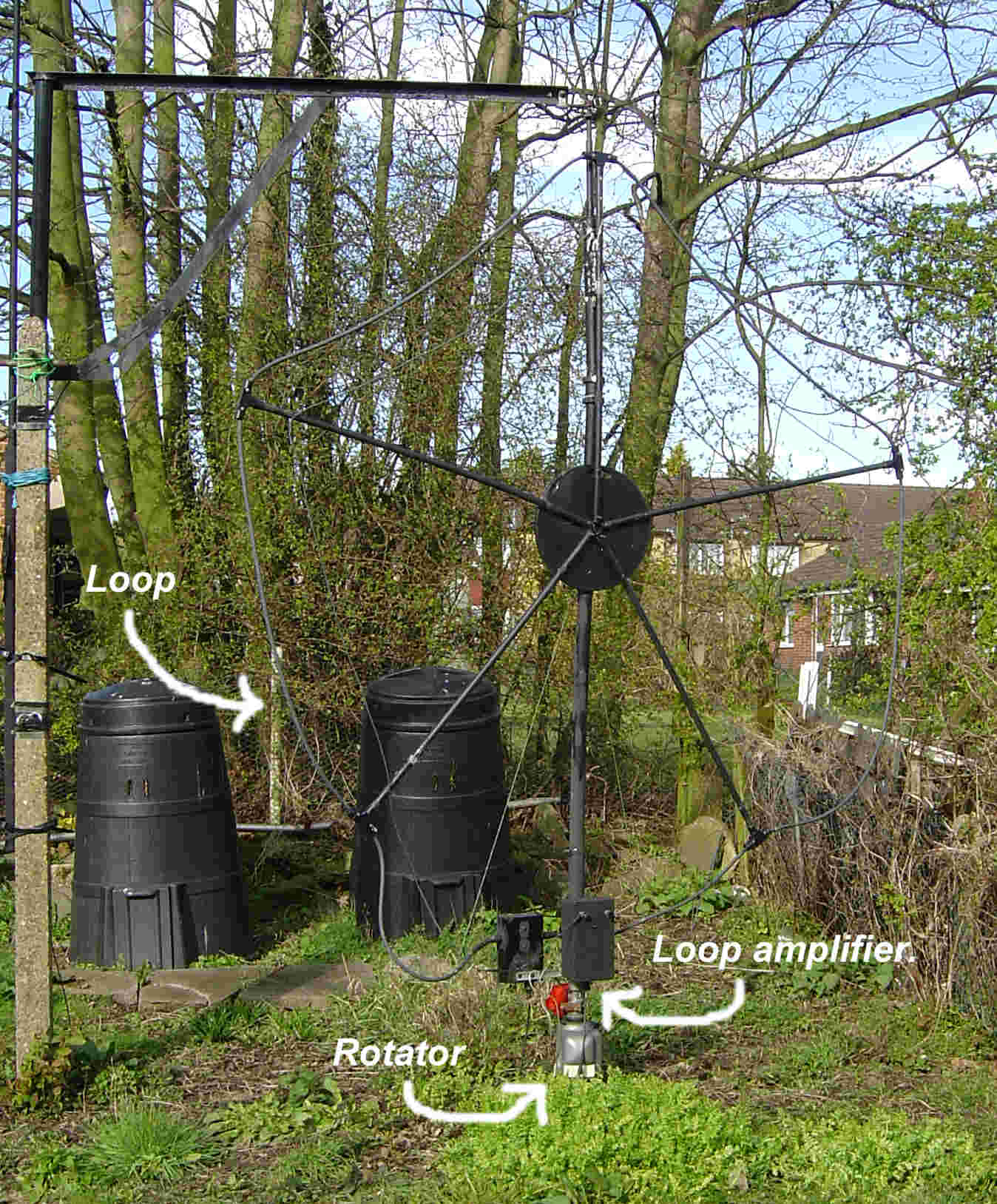
heat-sink to be glued to each device. The loop itself is made from multi-strand
(1.5 square mm) flexible wire supported on a pentagonal frame made from plastic electrical
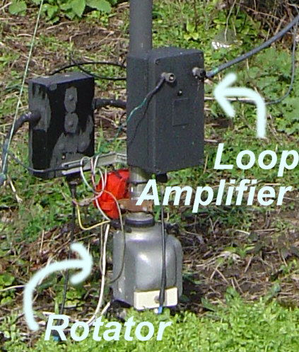
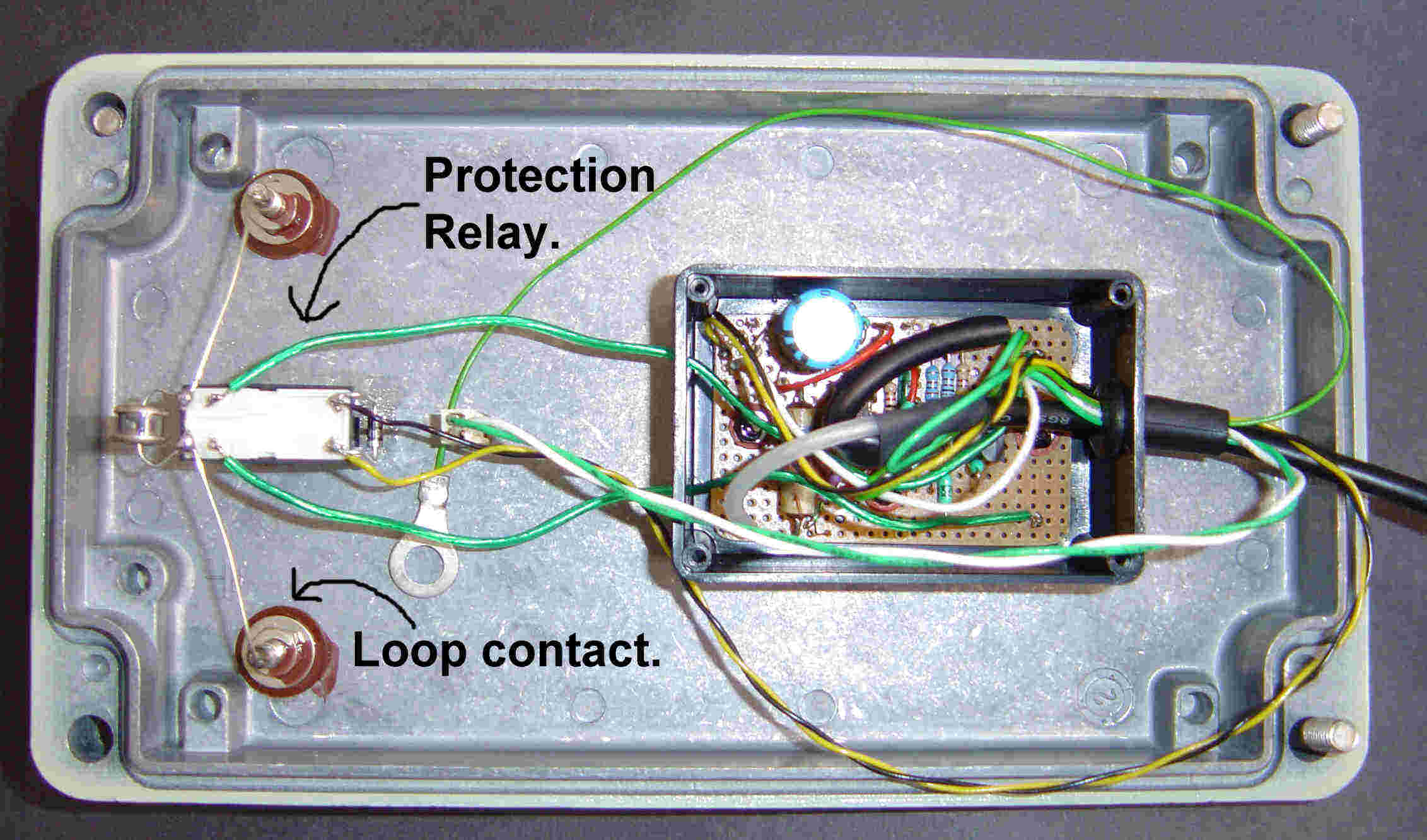
conduit. The relay shown in the loop amplifier circuit diagram protects the
devices from strong signals due to the loops close proximity to the
transmitting antenna. The relay has normally open contacts which close when the
amplifier is powered up for receiving and open when the power is removed for
transmitting or when the loop is not in use. The relay type is not critical
though it should have low contact resistance. The diode (D2) across the relay
coil protects the rest of the circuit from the relay coils reverse E.M.F. when
the power is removed and also acts as reverse polarity protection. While
nothing can protect the antenna from a direct lightening strike the open relay
contacts do offer some protection from surges caused by nearby thunderstorms.
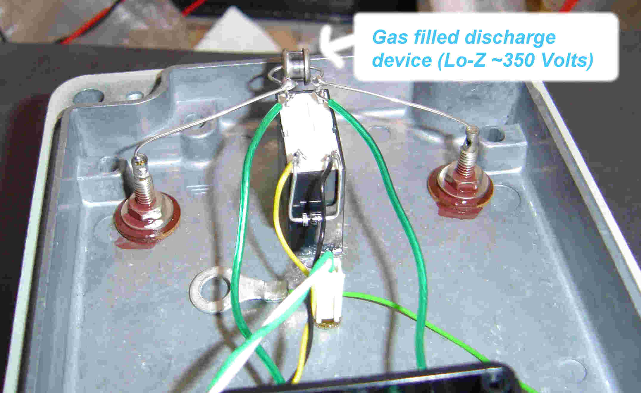
The loop also has a gas discharge device connected across its terminals
providing a second line of defence against surges. The discharge device itself
was salvaged from an old modem. Provision has also been made to disconnect the
coax cable at the antenna end to prevent currents induced in the coax from
damaging the loop amplifier during thunderstorms. Transformer (T1) serves a
dual function of both RF transformer and R.F. choke.
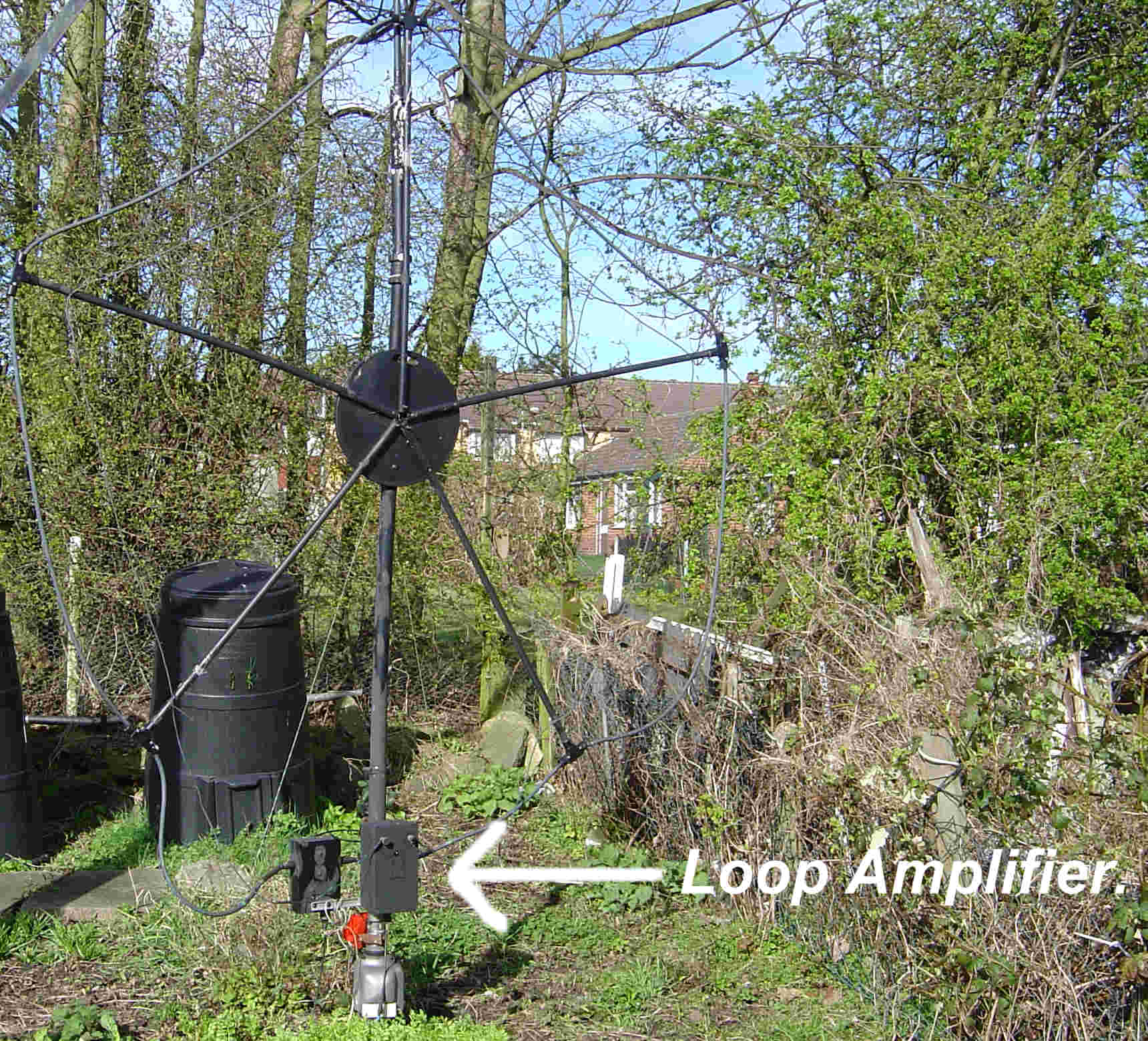
Because most of
the local QRM is thought to be due to conducted and radiated emissions from the
mains wiring it was decided to place the antenna outside at the bottom of the
garden as far away from the local noise sources as possible. The signal is fed
back to the shack via 20 Metres of RG58 A/U coax. The same coax provides a +12
Volts DC supply from the shack to power the loop amplifier. The supply unit to
feed power down the coax follows standard practice except for the optional
inductor “L2” (see loop amplifier supply circuit) which is to prevent “surges”
or DC from entering the receiver antenna input in the event of the DC blocking
capacitor (C1) failing. If such a failure should occur then L2 would provide a low resistance
path for the D.C. supply to ground (0 Volt rail) blowing the safety
fuse and protecting the receiver input from damage. In normal operation
the inductive reactance of L2 is high enough such that it will
not
effect the passage of R.F. signals to the receiver. The loop amplifier is mounted in a “chunky” alloy box
with all cable entry/exit points sealed with a waterproof sealant. Two small
bags of “Silica-Gel” (desiccant) have been included to reduce residual moisture
and condensation within the enclosure. An L.E.D is also fitted to the enclosure
to confirm the power is present. When used for SW listening the loop is powered
from a “wall wart” power unit, when the loop is used for transmit/receive
activity power is taken from the rig’s PSU via a separate unit (not shown)
which provides both antenna and supply switching.
Possible improvements and things to try.
In order to improve the antennas high frequency performance
it may be worth trying different devices with a higher frequency cut-off and/or
a lower noise figure. Using a pair of matched devices may also give improved
performance by virtue of the reduced distortion. Using devices capable of higher
collector dissipation it should be possible to increase the standing current
and further improve large signal handling capability. In an e-mail exchange John (G8CQX)
pointed out that “If you keep the collector resistors high and double the
supply voltage you might find it works better as the increased open loop
voltage gain will increase the feedback and reduce the input impedance further
improving the linearity of the amplifier”. During the testing phase it was
found that a good test for overloading was to listen around 28 MHz after dark
when the 10 Metre band is normally closed. Assuming you are using a receiver
with good dynamic range then any trace of broadcast stations on that frequency
might indicate overloading within the loop amplifier or distortion due to a
pair of badly mismatched devices.
My loop antenna
is at a height of 1.8 Metres and some improvement in performance might be
expected with increased height. The loop also displays some directivity
(particularly on the lower bands) making it possible to “null” some sources of
interference or strong broadcast signals by rotation of the loop. Any
directivity observed on broadcast signals in daytime all but disappears after
dark as the sky-wave propagation increases. I would avoid making the loop much
larger than the 1.5 Metre diameter quoted, while a larger diameter improves the
strength of lower frequency signals it risks overloading of the loop amplifier
due to strong SW broadcast signals.
Note:
In the event that this antenna causes "overloading" to the receiver it is
connected to then it might be tempting to reduce the gain of the loop
amplifier and/or reduce the loop size. However, I would refrain from
this coarse of action unless the loop amplifier is itself overloaded.
In my opinion a better coarse of action would be to fit an attenuator
at the shack end of the coax feeder in order to preserve the best
signal-to-noise ratio possible. Any noise picked up on the coax line
will be less of a problem if the signal-to-coax-noise ratio is kept as
high as possible.
Closing comments.
Using the receiving loop described it is again possible to
enjoy general SW listening and operation on the lower HF amateur bands thanks
to the significant reduction in the level of QRM. As an example, using a long
wire antenna noise on the 80 Metre band was typically S8, the loop has reduced
this to S1 or better. The loop has been successfully used to receive signals
from L.F. (60 kHz MSF time signals) to 30 MHz. The receiving loop has also
proved successful for receiving very weak signals associated with QRSS
operation within the 20, 30, 40, 80 and 160 Metre bands. If you are also troubled by local QRM sources
on the lower HF bands then give this antenna a try, you may be pleasantly
surprised at the results.
My thanks to
John (G8CQX) for giving his permission to reference his excellent
design.
The "Technical Topics" column of the June 1986 edition of "RadCom" (The R.S.G.B.s monthly publication)
“HF active receiving loop antenna” by John Hawes, G4UAZ (now G8CQX)
Well, that’s about it, thank you for reading this and please send any questions, comments or "heckles" etc to the e-mail address linked below.