Before I go any further I respect the fact that it has taken me some time to produce this write-up (sorry about that) and some of you out there have been "keen" to just look at the schematic so if you don’t' have any interest in how I arrived at the design and would rather go straight to the schematic then just click the link below. Then after looking at the schematic you will ask, "why on earth did he do that....." and then you will probably come back here to answer those questions.
Both the single "crystal gate" and the "lattice" filters are very similar in design, theory and construction. Beware! The simple circuitry of these types of filter masks a number of possible "pitfalls" so please don’t' rush to switch your soldering iron on just yet.
As a starting point I decided to read all the material I could find on this type of filter. I was very disappointed to find that information on these designs is now "scarce" and in most cases such information that is available is incomplete or misleading. What few texts are available often fail to explain what happens in the stop-band response of the filter. Amateur radio books written over the past 20 years have increasingly "dropped" the content on these types of filter in favour of the more modern "ladder" filters. As luck would have it though I found an excellent description of these filters in a 1939 RSGB book "Amateur Radio Handbook", Second edition, ninth reprint. This was written at a time when this type of filter was used extensively in amateur radio communications receivers. Receivers such as the RCA AR77 and AR88 used the single crystal type of filter with the AR77 having its "phasing control" brought out to the front panel.
Since all of my experiments with these filters are based on this chapter I have placed a link to this material here.
Not only is this a most detailed chapter on the subject but I have also found the theory is confirmed by my own experiments. One point needs stressing however, the chapter was written at a time when the "cut" of crystal and frequencies (typically 465 kHz) used in this circuit were very different from today. In our application some allowance has to be made when applying some of the theory to the practical design presented here.
Many of the explanations of how this type of filter operates I found to be often very misleading with two points in particular often being incorrectly stated. So I should like to put the record straight here. Firstly, the single crystal filter can and will produce a symmetrical band pass response which remains substantially symmetrical well into the stop band area. Symmetry is only limited or compromised by circuit imbalance. Secondly, the tunable "notch" in the filter response can only be used at the expense of a severely degraded stop band response.
Because the idea of using a simple xtal filter had a pleasing and elegant simplicity about it I felt this should be reflected in the final design too. This and the fact that I have very limited test equipment here at M0AYF led me to adopt the following design goals:
1) Simple design and easy to build in true qrp style.
2) A reproducible design (I hope).
3) Minimum of test equipment required to set-up and tune.
4) Very tolerant of crystal frequency. i.e. the ability to "pull" the crystal to the desired frequency is of prime importance.
The final point listed above was the subject of several hours of experimentation in order to develop some simple rules-of-thumb which can be applied to "pulling" the crystals and the impact this has on the filter bandwidth,circuit balance etc.
This is simply an emitter follower with a "not so high" input resistance (a few k-Ohms) such that it will not unduly effect the loading on the output of the test circuit. Adjustment of "RT" permits different termination impedances to be evaluated. Note the ferrite beads on the base and emitter terminals of the transistor which stopped annoying VHF parasitic oscillations.
The few references I did find using modern crystals in this type of circuit (as IF CW band pass filters around 1 to 4 MHz) seemed to favour a termination impedance of between 1 and 3 k-Ohms. This is in order to secure a reasonably narrow filter without "ringing". Using crystals at 10 MHz I found the termination impedance could be taken much lower than this with values of 200 Ohms being suitable. Much below this figure gave little further improvement in selectivity and simply resulted in unacceptable loss. The "nose" bandwidth of the filter is proportional to frequency such that at 1MHz the -3dB B.W. might be just a hundred Hz for a given termination impedance. At 7 and 10 MHz the -3dB bandwidth is typically around a few hundred Hz. Because of my lack of test equipment I deliberately operated the filter with as low termination impedance as possible to secure the sharpest "nose" I could. This made it possible to see the top of the filter pass band using a noise source and the D.C. receiver connected to a P.C. running "Spectran" audio spectrum analysis software by I2PHD. An excellent article on using this method to evaluate ladder filters written by Eamon Skelton (EI9GQ) appears in the April 2006 Rad-Com on page 28 along with a simple design for a noise source.
The evaluation circuit shown above yields a very poor filter with a highly asymmetrical band pass response. This is caused by the parallel capacitance of the crystal holder resonating with the motional inductance of the crystal to form a parallel resonant circuit and a resultant "notch" in the response. The position of this "notch" in relation to the series resonant frequency of the crystal (without any neutralization) can be of the order of 15 to 25 kHz away (at 10 MHz) from the series resonant peak and is dictated by the ratio of the crystals holder capacitance to its motional capacitance. Out of curiosity I measured the position of the "notch" relative to the "peak" for three HC49 crystals of 8, 10 and 20 MHz and found the "notch" to be 8.5 kHz, 11 kHz and 16 kHz away from the peak.
In order to achieve a more symmetrical response it is necessary to neutralize this capacity. This is achieved in the circuit below by the capacitor "Cn" which is adjusted to neutralize the crystal holder capacitance. I measured the holder capacitance of several HC49 type wire ended crystals in the 4, 6, 8, 10 and 20 MHz range and found the parallel capacitance to be around 5 to 6 pF. This gives a good indication of the value of "Cn" required. In my tests I used a 3-30pF "Beehive" trimmer capacitor which happened to be at hand for "Cn".
Out of academic interest the effects of the holder capacitance can be negated by placing an inductor across the crystal such that it resonates with the crystal holder capacitance. This arrangement was popular in some high grade German receivers built in WW2, the technique seems to have been "re-invented" a number of times since. One of the advantages of this arrangement is that it does not require a center tapped transformer but the disadvantage is that due to the low values of holder capacitance for the type of crystals we will be using (typically 5 or 6 pF) the inductance can be relatively large. It is also an advantage to be able to vary this inductance for "trimming", in view of the additional complications I decided to use the transformer method but I mention it in case others may wish to experiment with this approach.
My broadband antenna is also of unknown impedance so the input match may not be optimal, my experiments indicated it might be better to "step up" by about 1:4 but someone else’s situation may be different so for now I have left it as 1:1 which works well and is a good starting point. The input impedance of the DC RX I intend to use with this filter is also unknown so this could also benefit from careful matching. I would recommend to anyone building this filter to take the turns ratio of "T1" and "T2" as a starting point, the arrangement shown works but it may be possible to optimize the source/termination impedances better. The tuned circuit I/P transformer used in the testing phase was dropped because it did not offer any obvious advantage. "Peaking" of the tuned circuit reduced insertion loss as expected but the changing impedance as the circuit was tuned around resonance also altered the bandwidth. So for added simplicity, ease of construction and reduced component count I chose to use the broad band transformer technique for driving and matching the filter. After all, its the crystal that is supposed to be providing the enhanced selectivity with the "Q" of any addition tuned circuit being insignificant compared to the crystal "Q". The broadband transformer approach also makes for quick modification for other bands (3.5 or 7 MHz) with only the crystal and any "trimming" components requiring replacement. If the Filter is used on lower frequencies than 10 MHz then the pass band may need to be wider in which case the turns ratio of T2 can be altered to secure higher termination impedance.
This is were some of those "pitfalls" I mentioned earlier come in. First of all it is important to lay the circuit out "symmetrically" and if possible avoid "stray" capacitance couplings. This is important for two reasons.
1) Stray coupling from I/P to O/P should be minimized to avoid "leakage" of the incoming signal around the filter.
2) The stop-band attenuation suffers if there are too many stray couplings.
Click on the thumbnails below to see the full sized images.
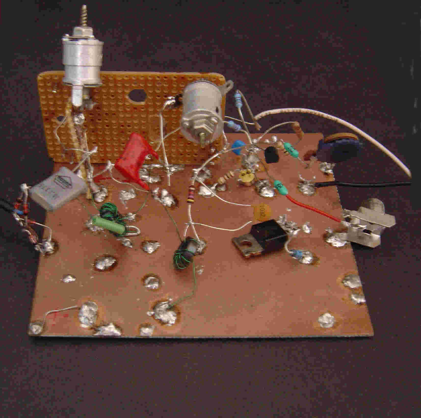
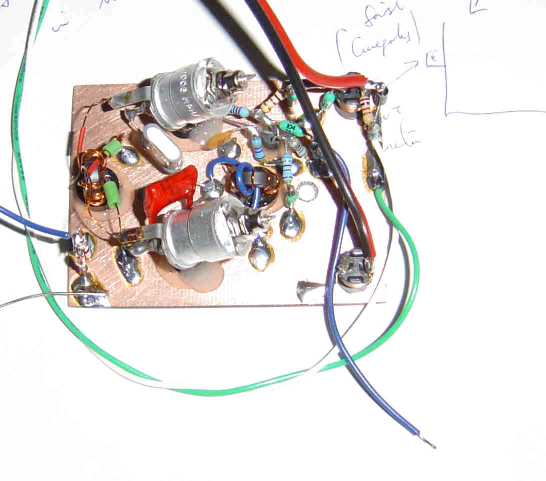
Just as some VFO circuits appear "simple" at first sight it very quickly becomes apparent that poor component quality or construction results in a poor VFO. This circuit is similar in some respects to a VFO in that the choice of components and construction should be of high standard for best results. The choice of components is very important, the insertion loss and filter "nose" are degraded if the inductors/trimmer capacitors etc are not of "Hi-Q" It’s a good idea to use a low loss component of good quality for the neutralizing trimmer "Cn", preferably ceramic. Any series capacitors found to be necessary for "tuning" should be silver mica or similar low loss type.
As I indicated earlier, test equipment here at M0AYF is very modest so I was forced to "improvise" a little and use what was available in true QRP style. Because I wanted to see the effects of component changes and tuning in "real time" I chose to use the noise source plus spectrum analysis software method described earlier. The noise source was a home brew unit, the details and schematic for the unit are shown here.
First set the capacitor "Cn" somewhere in the center of its range of adjustment. If your crystal happens to be "high" in frequency then you will need some inductance in series with the crystal in order to "pull" the crystal lower in frequency. If your crystal is low in frequency you will need some capacitance in series with the crystal. This is why I recommended leaving some space for a series capacitor/inductor in the "Construction" section.
Just as we can "pull" a crystal's frequency a little in an oscillator by adding some capacitance or inductance in series with the crystals own motional capacitance / inductance it is possible to do the same thing in this filter too. But just as there is a "Penalty" to be paid for pulling a crystal in an oscillator a similar kind of penalty exists when applied to this filter design. If a crystal is "pulled" too far in an oscillator the quality of the signal begins to degrade, amplitude of oscillation and general reliability all suffer. Most of the adverse effects are caused by the lowering of the effective "Q" of the crystal and by increased losses in the circuit. Not all crystals are born equal! A rule of thumb for how far a crystal can be "pulled" in frequency is about 1 kHz per MHz e.g. A 10.140 MHz crystal might be expected to be "pulled" around 10 kHz but this depends on the type of crystal. In any event this represents a figure for guidance only. In this filter the "penalty" manifests itself as increased insertion loss, reduced stop band attenuation and a flattening of the "nose" or broadening of the bandwidth. The effects only become serious problems if the "pulling" is taken too far. Should an individual crystal prove "difficult" it might be best to obtain another sample. Minor increase in insertion loss is of little consequence in view of the high noise levels on the 30 and 40 Mtr bands but if it should prove unacceptable then the optional amplifier can be added to negate the loss as already described. The other penalty of increased bandwidth is much less of a problem, even if the bandwidth doubles it still represents a very exceptional band pass filter compared to a tuned circuit.
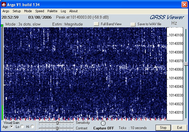
If you have to fit a capacitor or an inductor it is important that they are "Hi-Q", low loss components. In my case I had 3 crystals for use at 30 Mtrs (two 10.140 MHz and one 10.1376 MHz) and found my 10.140 crystals a little "high" requiring about 1.5 micro Henry of inductance to lower the resonant frequency slightly. The 10.1376 crystal required about 12 pF series capacitance to increase its resonant frequency. My personal preference was for the 10.1376 crystal and a series trimmer capacitor, I found this to be most convenient and easier to trim. Your crystals may require different values of series inductance or capacitance to bring them to the correct frequency. Using a noise source and ARGO in "Full Band View" mode it is possible to see the band of noise which represents the filter response. One method of tuning is to adjust the crystal frequency until this band of noise in centered just where you want it.
Click on the thumbnail below to see the full sized image.
Having brought your crystal to the desired resonant frequency the next job is to adjust "Cn" to neutralize the crystal holder capacitance and secure a more symmetrical response. The filter is essentially a form of bridge circuit and for correct operation it should be in a state of balance. First of all lets take the case in which you have been lucky enough to have a crystal which does not require any "trimming" in frequency. Apply the noise source to the antenna I/P of the filter and the O/P of the filter to a general coverage communications receiver. Set the receiver to 10.140 MHz and check you have a noise peak around that frequency. Now tune the receiver down by about 1 or 2 MHz (not critical) and adjust "Cn" for minimum noise from the RX. If you have no noise at any setting of "Cn" then increase the gain settings on the receiver and/or increase the noise level I/P to a point were noise is audible and again adjust "Cn" for minimum noise. You should find the "null" in the noise is quite sharp. Now tune the RX to say 11.5 MHz and re-check the adjustment of "Cn" You should find that if everything is working correctly the "null" in noise should be with "Cn" set in the same position as before.
If it does not behave as expected then "don’t panic".... yet! If you have added some series "C" or "L" with the crystal then you will have to compensate for this to restore the "balance" of the bridge. If you have added "C" in series with your crystal then you may have to add a small capacitor in series with "Cn" in order to bring the range of adjustment of "Cn" within reach of the "balance" condition. If you had to put inductance in series with your crystal then you may find you have to add some extra capacitance in parallel with "Cn" to bring the range of adjustment of "Cn" within reach of the "balance" condition. As an example I found a 10 pF capacitor in series with "Cn" corrected the "imbalance" caused by the 30 pF trimmer I had put in series with the 10.1376 crystal. The 10.140 crystal in series with 1.5 micro Henry inductance only required the capacitor "Cn" to be more fully meshed in order to secure balance. I did note when using a series inductor to lower the frequency of a 10.140 crystal that the stop band attenuation did not appear to be quite as good above the resonant frequency as it was below the resonant frequency. I am still unsure what cased this slight asymmetry and it may just have been some "leakage" around the filter or it could be related to the poor layout of my first prototype. It could also be that the low "Q" inductor used caused both a reduction in the pass band signal level and also reduced the stop band attenuation to some degree. In any event the degradation was not severe and posed no problems in practice since most of the AM broadcast "breakthrough" comes from the lower frequencies (6 and 7 MHz) so slight reduction in stop band attenuation above 10 MHz is less of a problem here in EU. If you have "Cn" correctly adjusted then you should find the filter response is fairly symmetrical. As a practical example here is a "real time" plot of my filter with a 7.020 MHz crystal fitted. A noisy plot but it conveys the general idea.
By contrast, below is an image of the same 7.020 MHz crystal with "Cn" incorrectly adjusted. Note how the stop band response is severely degraded by the incorrect adjustment of "Cn". The resulting "notch" would be to the lower frequency side of the central resonance peak but is "off-scale" in the image. In the example below the value of "Cn" is too high resulting in a notch below the center frequency and reduced stop band attenuation above the center frequency. If "Cn" is too small the situation is reversed.
The images of the 7.020 MHz filter gives some idea of the bandwidths possible at that frequency, at 10.140 the response is a little more flat for the same order of termination impedance. Depending on the termination impedance the typical -3dB bandwidths at 10.140 MHz appear to be in the order of a few hundred Hz to a few kHz. No adverse effects have been seen such as "ringing" etc though at the time of writing band conditions have been poor with very few strong signals close to 10.140 with which to judge the performance of "in-band QRM". Using the filter ahead of a communications receiver with a noise source connected to the filter input the response of the filter is able to reduce the noise signal to a point at which it can no longer be detected roughly 300 kHz above and below the the center frequency. Beyond those limits only receiver noise is audible.
Using the noise source connected to the input of the filter resonant at 10.140 and the output connected to the antenna of a communications receiver several "spurious" noise peaks could be detected. These appeared to be mainly above the center frequency of the filter and are thought to be spurious resonance modes within the crystal. The worst of these was at 10.230 Mhz and showing S4 on the signal strength meter relative to the S9 peak at 10.140 MHz. These spurious responses appear to be confined to frequencies of a few hundred kHz about the center frequency of the filter and mainly above the center frequency. This may warrant further investigation.
One subject not often talked about which may be relevant here is that of IMD caused by crystal filters. Not much seems to have been written about this subject so far and the only "snip" of information I have seen on the subject appeared in Rad-Com's "Technical Topics". A copy of the text appears here.......
It is possible that very strong signals arriving at the antenna may cause IMD in this crystal filter though at the time of writing this has not been observed.
Many of the texts describing this filter fail to highlight the fact that the use of an asymmetrical response in order to obtain a "notch" results in a severe penalty in terms of a degraded stop band attenuation on the opposite side of the resonance peak to the notch. This is particularly bad news for our requirements since the hope was to use the "notch" as a means of attenuating the image response of a DC RX such that a single signal response results. My experiments suggest that this would not in fact be a good idea, while it might be possible to secure some attenuation of the unwanted image it would come at the expense of a degraded stop band response above the filters center frequency.
In my experiments I found it was quite easy to secure a deep "notch" some distance away from the center frequency but achieving a "close-in" notch as might be required for attenuation of a DC RX image response proved to be impossible. With a 10.1376 MHz crystal in the filter I found a deep notch was possible about 11 kHz away from the center frequency but the depth of this notch reduces rapidly as it approaches the center frequency just as theory predicts. More investigation is needed in this area and could form the basis of new experiments.
Given that this simple circuit lends itself well to "pulling" of the crystals and has the feature of a tunable notch it may be possible to cascade two of these single crystal filters in order to secure the desired response. The symmetrical filter at the antenna to ensure good stop band rejection and a second filter with "notch" to give some degree of image attenuation. Any additional insertion loss of the combined filters could be negated by a high intercept, medium noise preamplifier if required. While the notch is not so deep close in to the center frequency it provides useful levels of attenuation 20 kHz or more from the center frequency so it may be possible to have the RX LO adjusted in order to make use of this deep notch.
Andy (G4OEP) has done some work on this type of filter (see note below) so I thought it might be interesting to see if I could replicate his findings and perhaps compare the single and twin crystal designs. Because it only requires minor modification to the single crystal filter in order to turn it into a lattice type I could not resist giving it a try.
The lattice filter is very similar to the single crystal filter in design, the most significant difference being the inclusion of a second crystal. The basic lattice filter is shown below.
I then experimented with the same methods of crystal "pulling" used in the single crystal circuit but had disappointing results. It seems that any attempt at "steering" one of the crystals resulted in loss of balance which proved difficult or impossible to restore. I came to the conclusion that with the lattice filter it would be better to select a pair of suitably matched crystals from a batch. This would then only require the crystals to be trimmed for holder capacitance differences. (see note below)
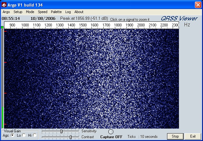
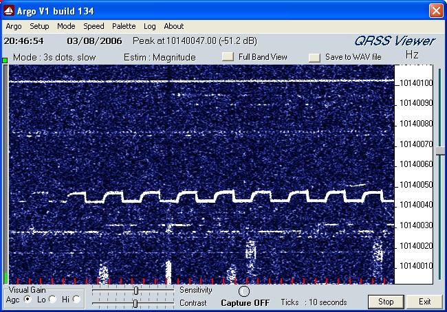
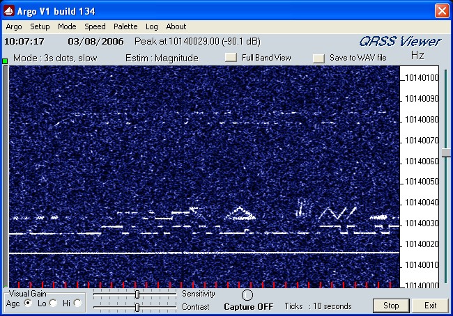
The results of the single crystal filter in use are very encouraging. Below are three screen captures from Argo showing "before" and "after" results of the filters inclusion into the signal path ahead of the DC RX. The first image shows the result of numerous AM broadcast stations "breaking through" while the second and third images show the results which have been obtained using the crystal filter. In both cases the AM breakthrough had been present prior to the filters insertion into the signal path.
Click on the thumbnails below to see the full sized images.
In addition to the images above I have made a couple of audio recordings to give an idea of the improvement in performance which resulted from the inclusion of the filter.
Click this link to hear what the DC RX sounds like without the crystal filter fitted.
Click this link to hear what the DC RX sounds like with the crystal filter connected..
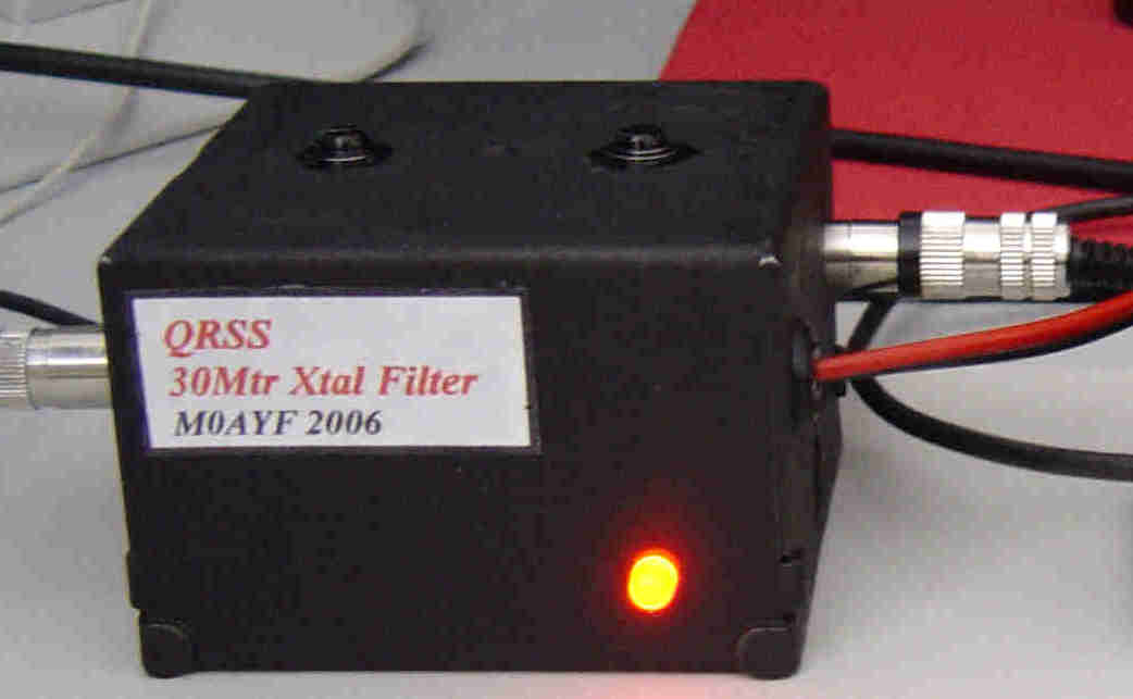
I was very pleased with the improvement this filter made and shall make it a permanent fixture in my QRSS DC receiver used here at M0AYF. Although the filter response is far from ideal its still performs many times better than any "LC" filter of comparable simplicity. The circuit is very versatile and lends itself well to tuning and "tweaking". Requiring only one crystal it represents QRP cost too. Because of a lack of crystals and the requests to present my findings using the single crystal filter I was not able to fully evaluate the lattice filter so the following comments are based only on my limited testing of this filter and information I have read.
Requiring two crystals the lattice filter provides a much better response though crystals placed in this circuit do not appear to lend themselves to tuning and tweaking as readily as in the single crystal filter. The lattice filter would perhaps benefit from the two crystals being selected and matched from a batch in order to secure the possible advantages the filter has to offer. This was the technique used in the 1960's when this filter enjoyed popularity among the amateur community thanks to the "surplus" crystals which became available in large numbers at that time.
Well, that’s about it, thank you for reading this and please send any questions, comments or "heckles" etc to the e-mail address linked below.