EXPANDED SCALE DC VOLTMETER
Peter Wokoun, Sr, Ewa Beach, Hawaii, January 2007
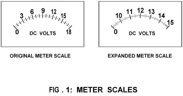
When using an analog meter to set the output of a power supply used for testing 12-volt equipment, an expanded voltmeter scale has a decided advantage and accuracy over a linear scale. Figure 1 shows the original meter scale and the expanded scale used in this example.
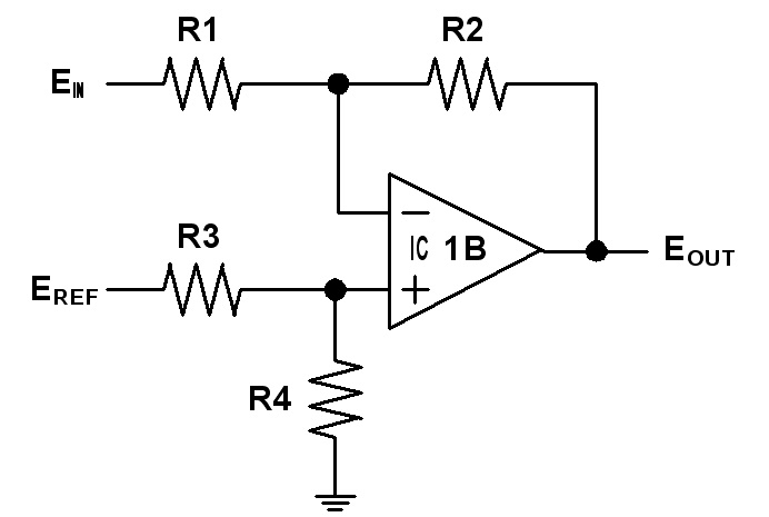
Figure 2 shows the schematic diagram for the expanded scale DC voltmeter.
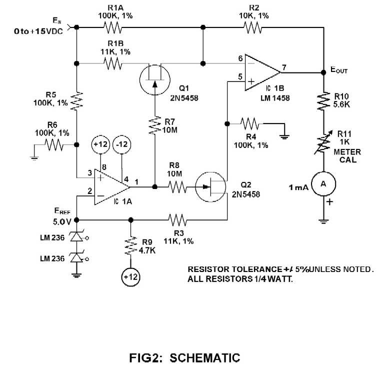
Figure 3 shows the operating curve for this circuit.
The design of this circuit can be split into two operating regions as depicted in the operating curve.
Below the curve's inflection point in the linear region the circuit simplifies to a basic inverting amplifier:
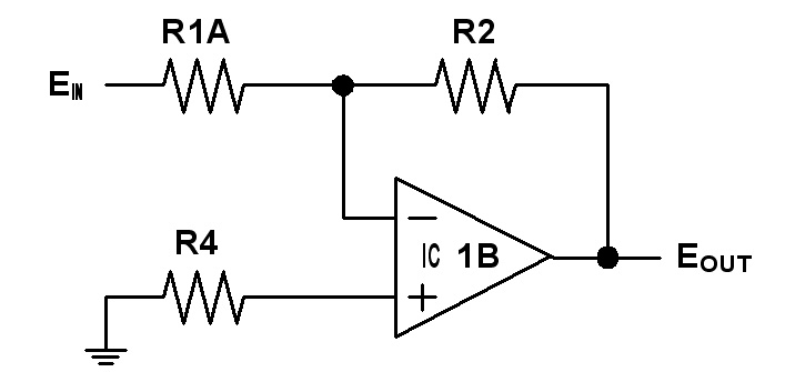
Eout is determined by: 
For this circuit this reduces to:
Eout = - 0.1 Ein
Above the operating curve's inflection point in the expanded region the circuit becomes a differential amplifier as such:
where
Eout is determined by: 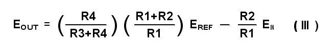
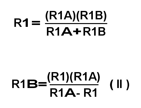
Eref is a 5-volt reference voltage set by the two LM236 reference diodes. Keep R2 and R4 the same values as in the linear region. Setting R1 = 10K gives a 1 volt output for a 1 volt input relationship in the expanded region. Calculate for R3 when at the inflection point when Ein = 10 and Eout = -1. Note that R1 here is the parallel combination of R1A and R1B. For higher accuracy the resistance of the JFETs of about 150 ohms can be included in the calculations of R3 and R1B.
After the calculations the expanded region of the operating curve for this circuit reduces to:
Eout = 9 - Ein
One of the LM1458 op amps (IC1A) is used as a comparator to drive the gates of the JFETs (Q1,Q2) which switches the other op amp's (IC1B) configuration between the inverting and the differential amplifier. The point where the comparator switches is the inflection point on the operating curve, i.e. where the meter changes from a linear scale to the expanded scale.
To set up for different ranges, the R5 and R6 divider determines where the comparator switches. If desired to start the expanded portion below 5 volts, a single LM236 can be used providing a 2.5 volt reference voltage. For other ranges the resistors will have to be recalculated from the above equations. Note that at the inflection point Ein and Eout must be the same for both equations (I) and (III).
Only a single adjustment is required by applying a 15-volt input and adjusting the meter cal potentiometer R11 for exactly a full scale meter reading.
The total current required from the + and - 12-volt supplies does not exceed 4 mA. The drain and source leads on these JFETs are also interchangeable.
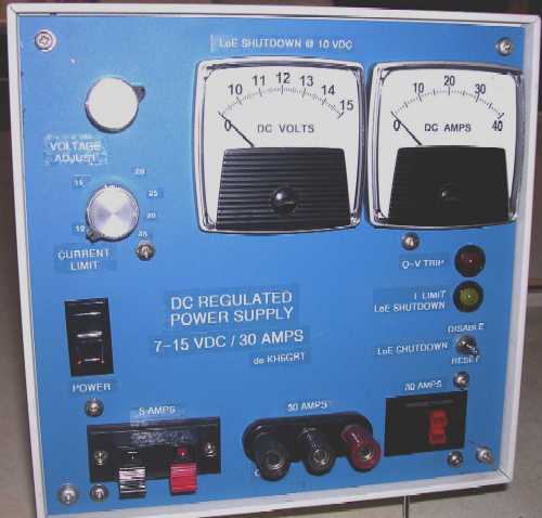
I incorporated this example meter into my high current 12 volt power supply. The meter looks like this installed into the power supply:
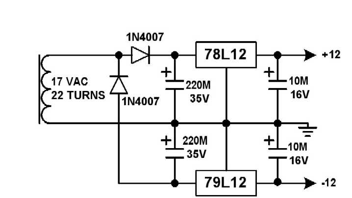
A suitable power supply for the meter circuitry like the one I used in the power supply would be like this:
![]()
![]()
![]()