R-390 / R-390A LINE AND CARRIER LEVEL REPLACEMENT METERS
Most R-390/R-390A enthusiasts know there are far more receivers than line level and carrier level meters for them. This is because the meters were scrapped when the receivers were removed from service due to their 'slightly radioactive' glow-in-the-dark meter pointer. Waiting for a receiver to become a parts unit to obtain meters can lead to a long wait. And those that do make it to market demand a hefty price approaching $150 or more for a pair on that E-place.
With a little ingenuity you can get a couple of similar-looking meters to work. The carrier meter has proven to be the most difficult because of the original's very high sensitivity. The original carrier meter has a 1 mA current rating with an internal resistance of only about 18 ohms. This gives you a meter with full scale only requiring 18 millivolts. Other meters found have a typical full scale sensitivity of 100 millivolts or more. The meter circuitry in the receivers won't let these other meters work because of their much higher internal resistance even though they may have a current rating much lower than 1 mA. What's required is a DC amplifier that amplifies the original meter's 18 millivolt sensitivity to the replacement meter's sensitivity.
These days, finding reasonably priced surplus 1-3/4" square black military-looking meters that you can convert for use is becoming near impossible. They seem to have disappeared from the scene. I found a very small cache of new 1-11/16" square Vu meters that I modified for use in the receivers. The meters were rescaled to have scales similar to the original meters. The meters selected for line level use were ones most accurate at the 0 dBm point. For others used as a carrier level meter the internal meter rectifiers were removed and a small printed circuit board with a DC amplifier was added to the rear of the meter. This DC amplifier presents the same 18 ohm resistance to the receiver that the original carrier level meters do. Each meter is electrically zeroed and calibrated to track closely with an original carrier level meter. And since both the line and carrier level meters look the same the receiver still maintains a'balanced' look.
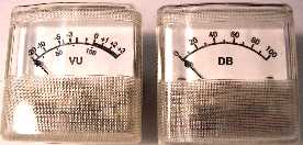
Here are the visible physical differences: the originals have a black scale background with white lettering and a metal/glass front. These replacements are reversed, having a white scale background with black lettering and a clear plastic face. The meters could have been reworked with white meter pointers but it would've required a LOT more work because the movements would have had to be rebalanced for the additional weight of the paint on the needle. Going further, you need to ask yourself if you could tolerate your receiver with non-original meters or keep it meter-less until you find some originals to stick in. If it's the latter, keep looking and good luck. You can also consider using non-original meters until you find originals and then sell the non-originals to someone else.
If you decided that you might want to try some non-original looking replacements until you get your originals, what do you need to do to get these replacements installed? Unfortunately, the mounting screw locations for the replacements are slightly smaller than the original mounting holes. The originals have a 1-9/32" mounting hole center-to-center spacing. These replacements require a 1-8/32" center-to-center spacing. This means you have to slightly file the mounting holes inward on your front panel or run a #15 (0.180") drill through them. Having to redrill or elongate the original mounting holes on the front panel may turn off a lot of folks. But consider this: we're talking less than 3/64" here or about 1 mm. That's 0.04" inward on each mounting hole. For comparison, an 18-gage wire is also 0.04" in diameter. And when you get a pair of original meters they will completely cover the slightly larger holes. Note, these dimensions are taken from my Stewart-Warner R-390A. Others should be the same but I'm not guaranteeing it.
The line level meter just requires the two wires going to the original meter. Polarity is not important. For the carrier level meter, in addition to the two wires going to the original meter, you need to run two additional wires to nearby tie points on the rear of the front panel to obtain a ground and 6.3 volt AC connection. The 6.3 VAC is rectified and filtered on the printed circuit board to power the DC amplifier that drives the meter. Don't worry about the current, the DC amplifier draws a maximum of 0.0005 amps! The 6.3 volt AC power connection is taken from the terminal strip TB101 terminal 1 and the ground connection goes to the ground lug that C101 on the R120 limiter control switch goes to. After installation you just touch up the meter zero potentiometer on the top of the IF module. You should have some soldering skills to put these meters in because the front panel components are fairly tight together. Dropping the front panel would make installation a whole lot easier.
These replacement meters also give you two additional features most original meters don't have. They have a mechanical zero adjustment and internal illumination lamps. To get to the mechanical zero adjuster you just pop off the front cover. The internal lamps have two additional terminals on the rear of the meter. These lamps appear to require about 8-9 volts to light sufficiently for daytime use or you can just put the 6.3 VAC to them and they have a nice glow that's sufficient for nighttime use. These lamps draw only about 30 mA. These little lamps light the meter scale from the front and not the rear. These are the first I've seen this arrangement in such small meters. Take note, though, I don't know from whom or where you would get replacement bulbs.
Like I said before, I have only a very small number of pairs of these meters. At this time I'm not selling them individually, just as a matched set. If there's not enough interest in sets then that policy could change. What keeps me from offering more of them? (1) Finding suitable meters, and (2) finding LM308N op amps I use for the DC amplifiers. Notwithstanding the time it takes to put these together, they are essentially being sold for just my costs.
Click 'here' to see what they look like on my R-390A.
Interested in what's involved in modifying the meters? Take a pictorial tour by clicking 'here'.
![]()
![]()