|
|
home |
scanner |
rig |
HT antenna |
base antenna |
links |
e-mail me
|
Home -> Base Antenna
My First Homebrew Antenna
-
2m Collinear J-Pole - okay, I'm a new ham. I got a low power 5 Watt radio, fully charged. I just
joined a local radio club, and my first net is tomorrow. What's missing here?
Well, I found out rather quickly that my HT's little antenna can't open up
the club repeater from inside an apartment complex.
Fortunately, I have been doing a bit of research on the web, and came upon this
great antenna project from the
KB1DIG Antenna Projects.
This is a 2-section collinear J-Pole antenna. It has the advantages of both
a 2-section collinear, and a J-Pole. And I have all the parts at home.
It sure does a nice job of getting the radio waves out of a large
apartment complex.
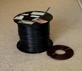 Fig 3 - Parts for the antenna - just a few feet of RG-58 and a short length of twin-lead
|
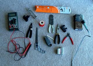 Fig 4 - Tools needed to build the antenna, including some clothes line and a
popsicle stick
Fig 4 - Tools needed to build the antenna, including some clothes line and a
popsicle stick
|

|
Fig 5 - Here are the
plans
for building the antenna from KB1DIG.
-
Description - The antenna consists of a 1/2 wave radiator at the top, another 1/2 wave
of wire coiled up in the phase element, a second 1/2 wave radiator below
that which is in phase with the top radiator, then a 1/4 wave J-Pole
section with a tap at 50 ohms.
There is a small loop at the top tied to the clothes line so that
the antenna can be hung off the top of the PVC pipe. Check out Fig 1-4
for some shots of the antenna and the material and tools I used to build it.
Click on Fig 5 to jump to the plans by KB1DIG.
-
Customizations - of course, I had to personalize the antenna from
the stock design. First, the important, is SWR. I found that the
measurements for the plan works well when the antenna is hung from
the ceiling, but when encased in PVC, the SWR shot up. By shortening
all the elements by 5.5%, I was able to bring down the SWR.
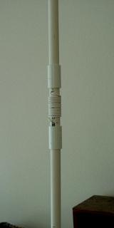
Second, for a leaner look, I used 1/2" PVC pipe instead of 3/4" PVC
pipe to house the antenna. Third, I decided to wind the phase element
on the outside of the antenna (Fig 6). The antenna is divided into 3 smaller
sections of PVC joined together with PVC fittings. Fourth, instead
of using circuit board, I used clothes line to tie the antenna to
a popsicle stick. Then I turn the popsicle stick to tension the wire.
I cut a small 1/4" notch at the top of the PVC pipe to hold the
popsicle stick, then trim off the wood sticking out the sides,
and the end cap gets put on.
|
|
| |
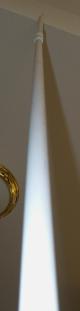
Fig 1 - antenna - looking up
|
| |
Fig 2 - antenna base
|

|
| |
Fig 6 - phase element
|
|
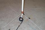
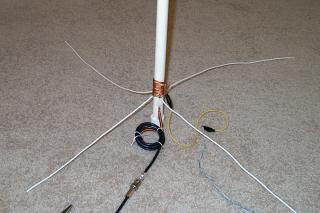 Fig 7 - The antenna base. The picture
shows the antenna ground with 4 x 1/4 wave radials attached, ground wire
to water pipe also attached to antenna ground, inductor made from 5-turns
of coax to block RF radiation from being coupled back into the radio
through the feedline shield.
Fig 7 - The antenna base. The picture
shows the antenna ground with 4 x 1/4 wave radials attached, ground wire
to water pipe also attached to antenna ground, inductor made from 5-turns
of coax to block RF radiation from being coupled back into the radio
through the feedline shield.
|
-
Antenna base - this is the challenging part of the antenna.
There are many elements coming together at the base (Fig 7).
The point in the base where the 1/4 wave radials are protruding
corresponds to the position of the 50 ohm tap on the J-Pole.
I used some of the left over braid from the coax. to bring the
antenna ground point outside the PVC pipe. The radials are
then soldered to the braid. A ground wire connecting the antenna
to a water pipe is also attached to the braid.
-
Below the ground point is where the coax. feed line enters the
antenna. Note that just outside the antenna, I have coiled up
the coax. feedline. I found through SWR measurement
that 5 turns of 2" diameter coil works best to block RF from
coupling to the feed line and going back into the radio.
| |
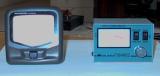
Fig 8 - SWR meters
|
|
-
Calibration - A SWR meter is required to calibrate the antenna (Fig 8).
A cross needle type meter is easier to use since there is no
calibration required before every measurement.
|
-
As mentioned above, I shortened the measurements of the elements by 5.5%. The
antenna is tuned to 146MHz. The length of the 1/2 wave bare wire elements
is c / 146MHz * 1/2 wave * 0.95 velocity factor = 98cm or 38.4", where c is
3 * 10^8 m/s. Shortening by 5.5% brings it down to 36.3". The phase element
is 12 turns. The 1/4 wave J-Pole element length is c / 146MHz * 1/4 wave * 0.82
velocity factor = 42cm or 16.6". Subtract 5.5% brings it down to 15.7".
Of course, I did check out the SWR before fixing everything in the PVC pipes,
which is done by taping the antenna to the outside of the PVC.
-
Essential to proper operation are the addition of radials for the ground
plane, and adding an inductor to the feedpoint. I soldered 4 x 1/4 wave
radials to the ground point. Also, I had 6 turns of coax. cable at the
feedpoint to bring down the SWR.
I am getting SWR of 1.3:1 in the center of the 2m band,
and 1.7:1 at the edges of the 2m band. The antenna seems to have
a very high Q. SWR rises quickly at the edge of the 2m band. The
antenna does not work at 220MHz or 70cm bands. The impedance and
SWR are way off outside of the 2m band. But, yes, it does pick up
signals in all bands :-)
73
[
home |
scanner |
rig |
HT antenna |
base antenna |
links |
e-mail me
]
|