

On Friday October 31, 1997, the PC Electronics model RTX-70 exciter that was originally used in the Brookdale ATV Repeater System was replaced by a new design to improve signal quality and add new system features. This page describes some the design considerations and new features possible with this new exciter, and includes schematics of the circuits designed during the exciter's development.
The ATV exciter described here uses a pair of Hamtronics model TA451 2-watt narrow-band FM voice transmitters to develop video and audio carriers on 439.250 MHz and 443.750 MHz. The TA451 is a single board, phase modulated exciter designed for amateur radio and commercial two-way land-mobile radio service. Several circuit modifications were made to each exciter to permit their use in this application.
In operation, one TA451 exciter is operated at 439.250 MHz and is amplitude modulated with video information, while the second operates on 443.750 MHz and is frequency modulated to produce a broadcast-standard FM aural subcarrier. The RF output of each exciter is combined in a diplexer and further amplified through several linear power amplifier stages.
Figure 1 shows the audio circuitry used to produce high-quality frequency modulation from each exciter. Line-level audio from the repeater controller is fed through a 15 kHz active low-pass filter (U1A), a 75 microsecond pre-emphasis network (R8, C5), and an automatic level control circuit (U1B). Automatic level control is used to prevent over modulation should the audio input to the exciter rise above normal levels. This method of level control generates considerably less harmonic distortion than audio clippers typically found in FM voice and some commercial ATV transmitters. Audio signal levels of 20 times above normal can be handled with this circuit without causing overmodulation or excessive distortion.
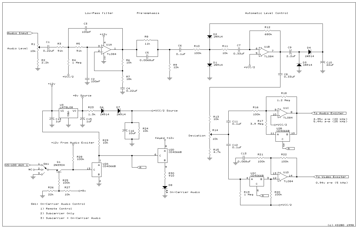
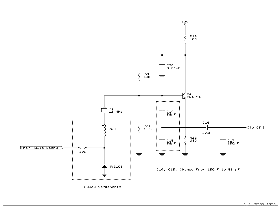
Audio is then fed through a pair of voltage amplifiers having different gains and opposite phase shifts (U1C, U1D). Each amplifier drives a varactor diode that is connected in series with an inductor and crystal in each TA451 exciter, thereby allowing direct frequency modulation of the RF carrier. A DC bias voltage produced by voltage regulator U3 and its associated circuitry is applied to each varactor along with the transmitted audio. This bias voltage is temperature compensated by diodes D6 and D7 to minimize frequency drift that would occur due to the varactor's temperature sensitivity. Since the TA451 exciters are virtually identical to one another, any drift that might occur due to temperature variations will be proportional in both units. This maintains a very accurate 4.5 MHz separation between the visual and aural carriers regardless if any drift due to temperature changes should occur.
The ATV exciter described here can transmit audio in a variety of ways including broadcast standard subcarrier audio, "on-carrier audio", or a combination of both methods. Subcarrier audio is produced by frequency modulating the TA451 operating at on the audio subcarrier frequency with a peak deviation +/- 25 kHz. On-carrier audio is produced by frequency modulating the video carrier with a deviation of +/- 5 kHz.
On-carrier audio allows reception of ATV signals by tuning to the video carrier frequency (439.250 MHz) with narrow-band FM receiver, such as a handheld UHF-FM receiver or scanner. A combination of both audio transmission methods is also possible with this exciter, allowing the greatest flexibility in ATV audio reception. When the combination is used, the frequency modulation fed to each exciter is done in opposite phase, and the deviation of the audio subcarrier is reduced from 25 kHz to 20 kHz. A standard television receiver will detect FM intercarrier audio as the difference between the visual and aural carriers. Since both are frequency modulated and are modulated in opposite directions, the receiver sees the difference as (+/- 5 kHz) - (-/+ 20 kHz), or +/- 25 kHz, which is the broadcast standard. As a result, no change in audio level is observed on a standard television receiver when the on-carrier audio feature of this exciter is turned on or off.
U2 provides an electronic switch for selecting the proper deviation required for each exciter when generating subcarrier audio, on-carrier audio, or a combination of the two. The switching is completely silent without even as much as a click or pop when the audio mode is changed. The audio transmission method may be selected by a front panel switch, or by remote control using an AUX output on the VS-100 ATV repeater controller. Should the subcarrier audio generator be turned off while the on-carrier audio is off, the exciter automatically switches the on-carrier audio feature on by default, thereby assuring that transmitted audio will always be heard even without the subcarrier generator in operation.
The video modulator used in this exciter is very similar to the video modulator designed by KD2BD in 1996 to improve the performance of several PC Electronics exciters. The first section of the modulator performs a video level clamping function. The high input impedance Darlington amplifier and the small series coupling capacitor combine to achieve an excellent low-frequency response and a clamping function with very rapid response time. A three terminal voltage regulator sets the clamping level at 8 volts.
The clamped video is then level shifted through a zener diode and applied to a single video amplifier stage. A PNP transistor in the collector circuit functions as a constant current source for the video amplifier. The use of a constant current source rather than a collector load resistor in the video amplifier results in very high voltage gain with nearly rail-to-rail output voltage capability. Negative feedback around the video amplifier reduces the gain to the amount required while it increases the bandwidth, flattens the frequency response, increases the linearity, and reduces any distortion products to extremely low levels.
A 2N3904 in the base circuit sets the `Q' point of the amplifier. A miniature green LED (Mouser ME351-1641) is used as a voltage reference in the emitter lead of video amplifier transistor to prevent the white modulation level from going below approximately 12.5%. An NTE236 RF power transistor serves as the last stage of the modulator. This transistor can develop 13-watts of RF at 50 MHz. A low-cost Toshiba 2SC1969 can also be used in this stage.
Clamped video is also fed into an LM311 voltage comparator that serves as a video sync detector. Sync pulses detected by this circuit trigger a CD4016B silicon bilateral switch that lowers the negative feedback around the video amplifier and voltage follower at sync time to compensate for high power gain compression in any solid-state linear power amplifiers that may follow the video modulated stages.
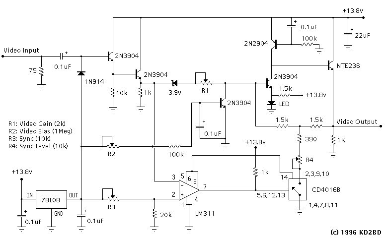
R1 is a video gain control. It is used to set the white modulation level. R2 is a video bias control. It is used to set the black modulation level. R3 is adjusted so that the LM311 delivers clean sync pulses to the CD4016B with an input signal present. R4 adjusts the sync modulation level. Up to 9 dB of sync expansion is possible with this circuit.
The following graphs show the results of a computer simulation of the video modulator used in this exciter when adjusted for a voltage gain of 20 dB. This simulation was performed using MicroCAP IV software, an electronic circuit analysis program by Spectrum Software.
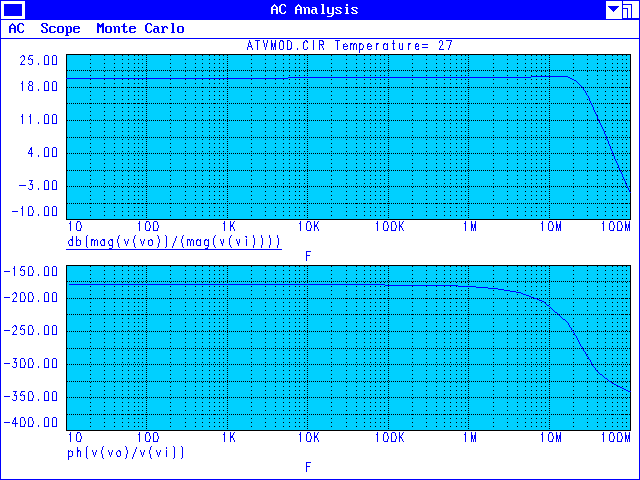
The top graph plots modulator voltage gain as a function of frequency. The graph shows a wide and flat frequency response that extends to 20 MHz.
The lower graph plots modulator phase shift as a function of frequency. The graph shows a wide and flat phase response that is essential for accurate color reproduction. The phase response around the chrominance subcarrier (3.58 MHz) falls well within the +/- 10 degree specification used by commercial broadcasters.
DC power to the video modulator and each RF exciter is controlled through a controller board that allows both local and remote mode switching, control of the audio subcarrier RF power level, and provides front panel LED indication of the exciter's status. Figure 3 shows the circuitry involved in the controller board.
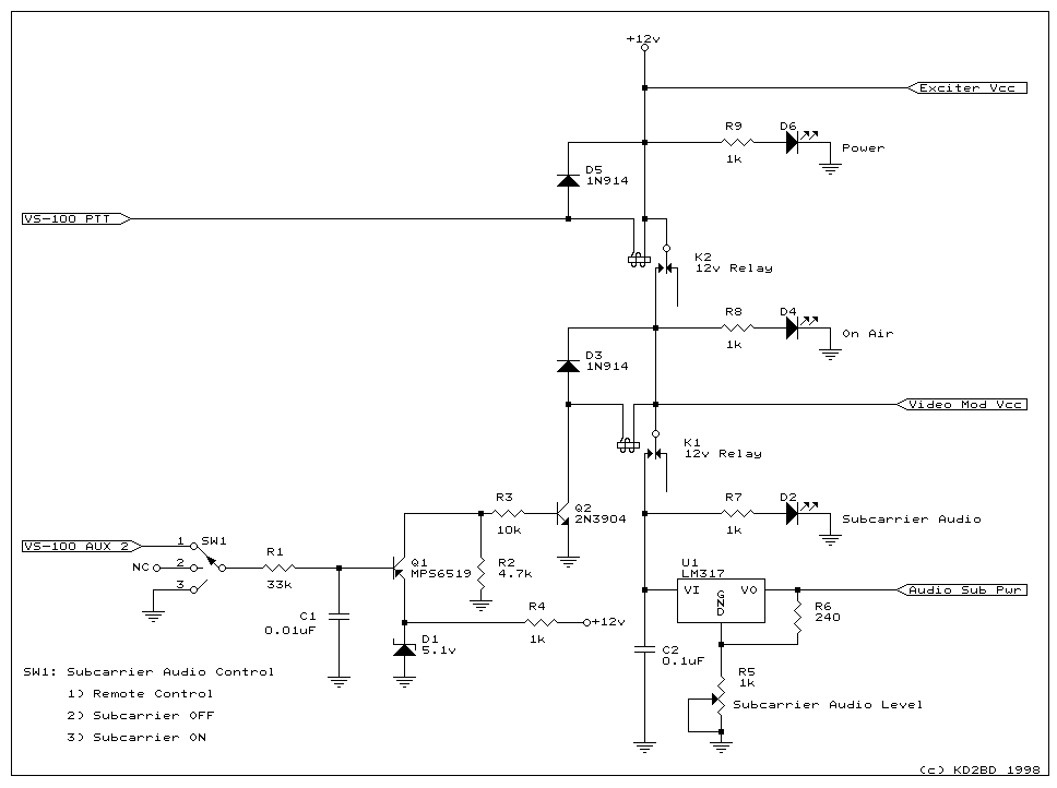
While the audio subcarrier exciter is not amplitude modulated with video information, it is nevertheless modified in the same manner as the video exciter to allow control of the collector voltage feeding the driver and RF power amplifier of the exciter. Instead of amplitude modulating the exciter with video, a regulated and adjustable DC voltage is applied by U1 to control the RF power level of the exciter. Potentiometer R5 adjusts the output voltage of U1 between 1.25 and 6.0 volts, and should be a multi-turn trim pot for easy adjustment. The DC output voltage available from U1 allows the audio subcarrier RF power level to be adjusted between -20 dB and -7 dB with respect to the peak visual power level. (-10 dB and -7 dB are standards for commercial broadcasters.)
Several circuit modifications are required of the Hamtronics TA451 boards to permit frequency and amplitude modulation. Referring to the TA451 schematic diagram, remove Z6, Z9, and C60. Jumper E1 to Z6, and apply amplitude modulation to the lead of C60 that connects to the collectors of the driver and final RF amplifying transistors. Direct frequency modulation is achieved by modifying the crystal oscillator circuit in each exciter in the manner shown in Figure 4:
For the ultimate in frequency stability, keep each crystal oscillator powered continuously, and key the frequency multiplier stages of each exciter with PTT logic from the controller board. The stability achieved when doing this rivals that of a CW transmitter on HF.
Deviation level control potentiometer R15 should also be removed from both boards since the phase modulator is not used in this application. If the TA451 boards are purchased as kits, the audio sections need not be constructed.
The RF outputs of the visual and aural exciters are combined using a Wilkinson power combiner fabricated from two quarter wavelengths of 75-ohm coaxial transmission line (RG-6/U). Each 75-ohm line connects to the output of each exciter, with the free ends of each line connected in parallel to produce a combined 50-ohm RF output. This simple power combining arrangement also maintains a fairly high degree of RF isolation between each exciter, a necessary characteristic for keeping IMD product generation at a minimum.
The two TA451 boards, the audio and video modulators, the control board, and a 12 volt regulated DC power supply were all mounted within a single 19" wide enclosure purchased from Sescom. An LM386-based audio amplifier was also added to monitor the transmitted audio at the repeater site through a small speaker. All circuitry was constructed on perforated circuit boards using point-to-point wiring techniques. PC boards were not designed for this project.
This exciter has delivered outstanding performance in over 10 years of continuous service. The application of independent aural and visual exciters has demonstrated a level of performance and flexibility that is well worth the added expense and complexity of the arrangement. The end result is a commercial quality television signal completely devoid of 920 kHz "beat" interference between audio and color subcarriers (the IMD of the power amplifiers that follow the exciter notwithstanding). In addition, no RF power is wasted in the generation of an audio subcarrier 4.5 MHz below the video carrier, as would result if a 4.5 MHz FM carrier were simply mixed with baseband video in the video modulator (as is the practice of virtually all ATV transmitter manufacturers). The audio subcarrier can be operated at levels equivalent those used by commercial television broadcasters (which are significantly higher than those possible with CATV modulators), ensuring excellent audio reception even under weak video signal conditions. The audio frequency response was designed to meet broadcast standards, and the on-carrier audio feature makes ATV audio monitoring simple and flexible.
Permission is granted to anyone to duplicate this circuit design provided it is used is for legal and non-commercial purposes only.
|
|
John Magliacane |