The half square, like any other linear-element antenna, can be set up in a parasitic arrangement to create a uni-directional array with gain and significant front-to-back ratio. In short, we have a 2-meter half square beam.
Between the time I made my original test 2-meter half square and the time I tried out the beams, I change construction to something more permanent. The horizontal member increased to 3/4" diameter. I have used both aluminum U-channel and tubing, and tubing has less tendency to twist. The vertical elements are 1/8" diameter rod. I have used both brass and aluminum, and recommend aluminum for long-term installations.
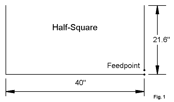
Figure 1 shows the dimensions of the tube-and-rod half square. Construction details will appear in the Communications Quarterly article.
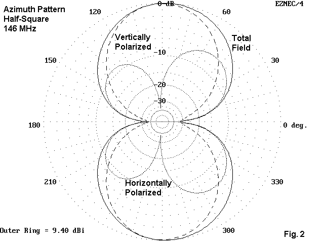
Figure 2 is an azimuth pattern of the antenna at 30' above ground at an elevation angle of 3 degrees. The vertical and horizontal components of the total pattern are clearly visible, and the revised half square performs as well as its predecessor--but handles wind with less tendency to reshape itself.
I have noted in the past that parasitic versions of the half square are possible. The number of requests for at least a few details is large enough that I am adding this note to the collection.
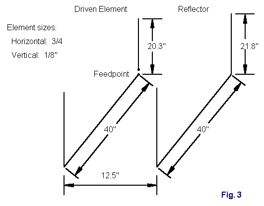
A 2-element half square appears in Figure 3. The arrangement is a typical driver-reflector array, with the spacing chosen to achieve a 50-Ohm feedpoint impedance. Note that the horizontal elements are identical in length, with only the vertical elements adjusted to achieve the pattern and feedpoint impedance. Actually, the spacing is not too critical: 12-13 inches shows no change in the SWR curve.
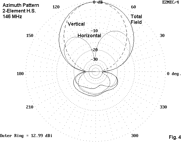
Figure 4 shows what we get for our efforts in adding a second element. The forward gain for this plot (taken under the same conditions as the plot for the basic half square) is about 13 dBi, 3.6 dB better than the single half square. The 180-degree front-to-back ratio is over 18 dB. The slight offsets in the pattern result from feeding one corner. The feedpoint impedance report from NEC-4 is 49.4 - 1.4 Ohms, which the limits of my measuring equipment confirms. The beam covers virtually all of 2-meters.
If we can have 2 elements, why not 3?
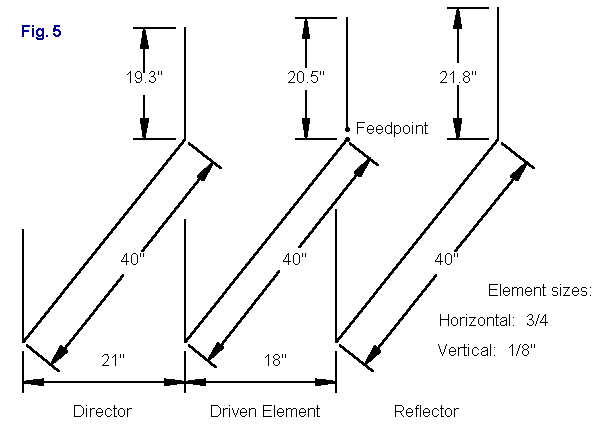
Figure 5 shows a 3-element version of the antenna, along with dimensions. Once more, the horizontals remain at 40" while the verticals change length according to their function. The element spacing also grows larger in the search for a balance between performance and feedpoint impedance.
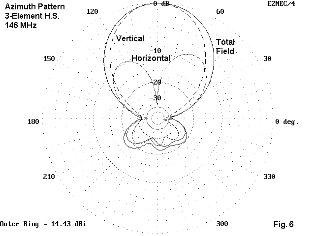
The azimuth pattern in Figure 6 (same modeling conditions) shows the added gain (1.4 dB) and the improved front-to-back ratio (22.6 dB). The feedpoint impedance is about 43 Ohms at resonance, and the operating bandwidth is a bit narrower than the 2-element antenna.
Also notable is the gradual narrowing of the beamwidth of the antenna. A Yagi set vertically will have a very wide beamwidth, defeating some of the directionality we desire from a beam. The half square beams have beamwidths comparable to a Yagi set horizontally, but the half-squares are mostly vertically polarized. This is the chief reason for building a parasitic half square: to achieve relatively high directionalness while being vertically polarized.
Whether the 3-element version is a justified endeavor depends upon a judgment that balances the added gain and front-to-back ratio against the added mechanical complexity. Six vertical rods makes a bristly array. I use lots of 1/2" Schedule 40 PVC, with the horizontals passing through Tee joints and pinned in place. Again, details will appear in Communications Quarterly. This note is only to whet your creative whistle and not to provide detail construction details.
A second way to add gain to the system is to stack arrays. Our original 2-element half square array provided about 13 dBi gain when at a height of 360" (30') What happens when we stack a pair in the manner shown in Fig. 7.
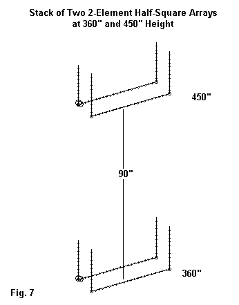
The sketch shows a recommended separation of 90", that is with the second array placed at a height of 450" (using the horizontal part of the array as a reference). Actually, this separation distance does not yield the highest gain. That comes with a separation of about 70" and reaches 16.4 dBi. However, the front-to-back ratio is only 14.0 dB. If we increase the separation to 90", we drop to about 16.2 dBi gain, but inprove the front-to-back ratio to 19.6 dB. As well, the feedpoint impedance for each array shows a value closer to the impedance of an independent array: about 56 -j3 Ohms. These values should permit stacking with standard coax-cable methods.
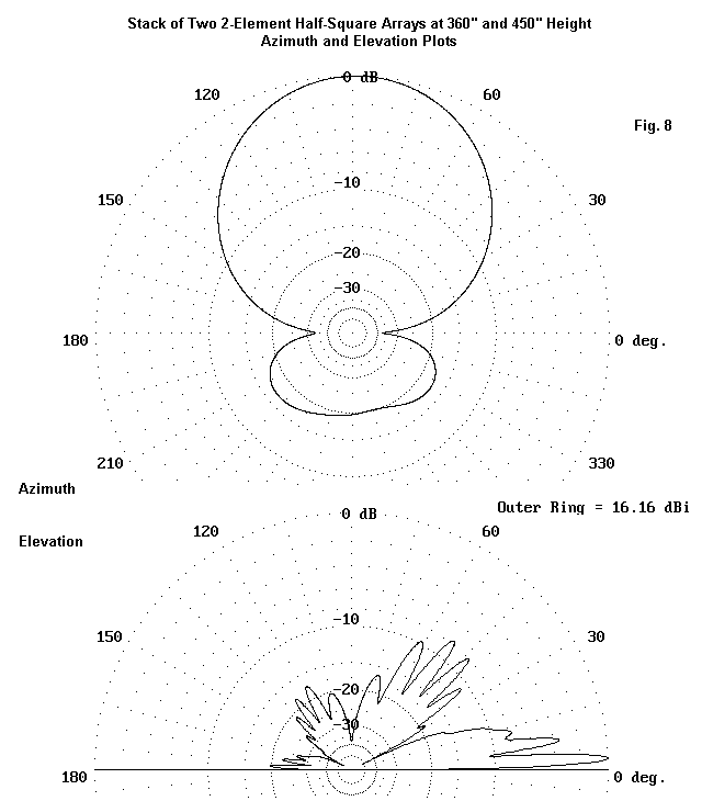
Fig. 8 shows the azimuth and elevation patterns for the stack. Otyher separations are possible, but the recommended 90" separation (about 1.1 wl) yields a good pattern with the shape of the original pattern for one array and 3 dB of added gain. We can apply the same technique to similar arrays, such as the one in the next episode.
If you are feeling really creative, consider this fact: a half square can be doubled to make a bobtail curtain with added gain. Will it also work at VHF?
Updated 4-12-99, 7-18-2002. © L. B. Cebik, W4RNL. Data may be used for personal purposes, but may not be reproduced for publication in print or any other medium without permission of the author. A more extended technical discussion of the antenna has appeared in Communications Quarterly.
Link to: L. B. Cebik, W4RNL
2-Meter Half Square I build My Link to Ham'er and the world Maps and my QTH
My life in pictures Second Link page Navigation rules Personal Floatation Device Boat Distress Signals
Latitude Longitude & Bearing US State & Cities HF Loop antenna