Update!
Version 2.2b boards and full kits with all parts and instructions
needed to build your own Antitrack are available.
Contact me for more details at [email protected].
This is my latest version of
"The
Anti-Tracker basic" by "RadioActive Networks"
The board is 1.9" x 2.5"
What is "The Anti-Tracker"? Basically it is a small PIC based system that decodes received APRS position packets and encodes the posistion reports into a GPWPL NMEA sentence to be sent into a compatible GPS unit. With the Anti-Tracker there is no need for an extra mapping display device such as a laptop or PDA. The stations received display directly on your GPS display and will move the symbol to the correct location anytime a new position is received.
This provides a way to have a fuction that was once only available on the Kenwood APRS enabled radios.

Here are the PCB designs I made since at the time Radio Active Networks did not have any available.
This version is 2.5" x 2.75"
The board is 1.9" x 2.5"
What is "The Anti-Tracker"? Basically it is a small PIC based system that decodes received APRS position packets and encodes the posistion reports into a GPWPL NMEA sentence to be sent into a compatible GPS unit. With the Anti-Tracker there is no need for an extra mapping display device such as a laptop or PDA. The stations received display directly on your GPS display and will move the symbol to the correct location anytime a new position is received.
This provides a way to have a fuction that was once only available on the Kenwood APRS enabled radios.
Here are the PCB designs I made since at the time Radio Active Networks did not have any available.
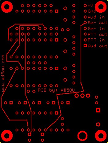
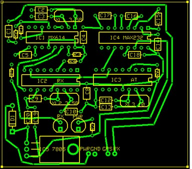
Antitrack PCB V2.2b
1.9" x 2.5"
The Antitrack only requires 4 external
connections. +V, Ground, Audio in, and Serial out. In this
version I added 4 extra pads to allow for a Byonics surface mount
version of the TinyTrak3 to be installed under the Antitrack via jumper
wires or 8 pin header.
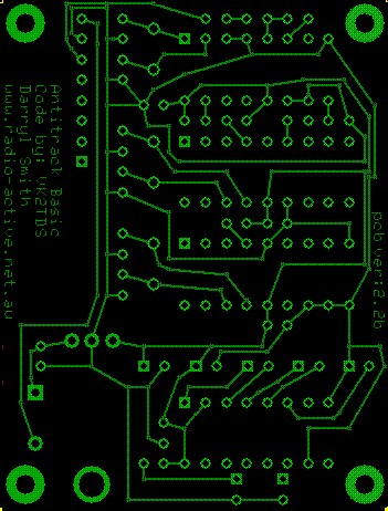
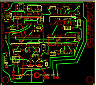
Antitrack PCB v1
This version is 2.5" x 2.75"
These designs came from the schematic
available on the RadioActive Networks page. For component values
refer to the schematic on their page or my redrawn version below.
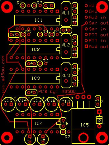
I made a couple of slight modifications to the schematic. I added
a "PWR" LED with an associated resistor (R7). I also added a
provision for a 7805 voltage regulator in case of higher current
requirements other than the anti-tracker itself. The schematic
shows a 78L05 since that's all the anti-track requires but since I had
7805's laying around and like the flexability of using the available 5v
supply so I chose the larger regulator. This board is only 1.9"x
2.5" with a little room to spare.
I have also designed a PCB for a Anti-Tracker combined with a Tiny
Track 3. The board uses my original board design and uses parts
from a TinyTrak3 kit. The Tiny Track
3
is available from www.byonics.com.
I have never actually built this board but will try to answer any
questions you may have if you choose to use this version.
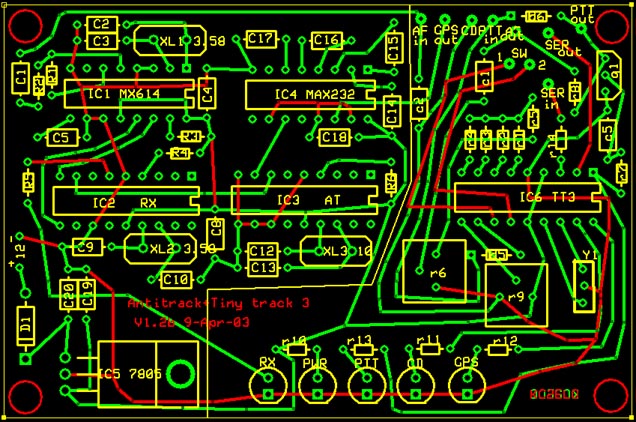
This board is only 2.5"x3.75"
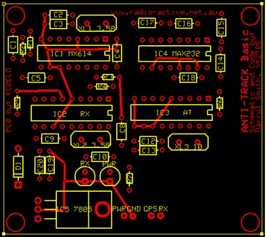
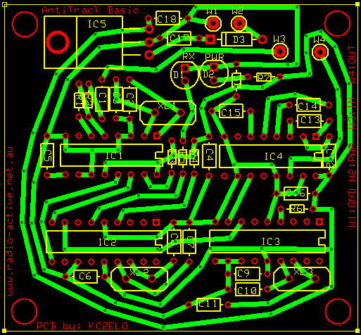
I also designed a single sided PCB with fairly large width traces that could easily be reproduced by hand with a simple PCB etching kit from Radio Shack etc.
I also designed a single sided PCB with fairly large width traces that could easily be reproduced by hand with a simple PCB etching kit from Radio Shack etc.
This board measures 2.75"x2.5"
(The component shown between D2 and R7 is a 0 ohm jumper)
If you would like to use and or modify my designs you will need the
"ExpressPCB" software and the pcb files I have listed below.(The component shown between D2 and R7 is a 0 ohm jumper)
These boards were designed using
"ExpressPCB" software available from www.expresspcb.com.
The software is free and also comes bundled with a schematic drawing
program.
Smaller
Version 2 Antitrack PCB
Original Stand alone Anti Tracker PCB
Antitracker + Tiny Track 3 combo PCB
Single Sided Antitracker PCB
Original Stand alone Anti Tracker PCB
Antitracker + Tiny Track 3 combo PCB
Single Sided Antitracker PCB
I also have a redrawn schematic using
the orginal design. (I just cleaned up the lines from the original a
little)
The image is in TIFF format and can be
read using Kodak Imaging that comes with most versions of Windows or
any
other compatible image viewer. Antitracker
Basic schematic in tiff format You can also download the
actual .sch file for use in "ExpressSCH" software bundled with
"ExpressPCB" ExpressSCH Antitrack Basic
schematic file
Parts list
| Qty | Item
Description |
Part ID's |
Source/part # |
Price |
| 1 |
MX614 (Modem Chip) |
IC1 |
Glitchbuster.com/ MX614P |
$7.47 |
| 2 |
PIC16F628 IC |
IC2, IC3 |
Glitchbuster.com/ 16F628-20/P |
$2.74 ea. |
| 1 |
MAX-232 IC (Generic) |
IC4 |
Glitchbuster.com/ MAX232N |
$0.69 |
| 2 |
16 Pin DIP Socket |
Under IC1, IC4 |
Glitchbuster.com/ ICS16 |
$0.17 ea. |
| 2 |
18 Pin DIP Socket |
Under IC2, IC3 |
Glitchbuster.com/ ICS18 |
$1.18 ea. |
| 2 |
3.57Mhz Crystal w/ 2 22 Caps |
XL1, XL2 |
Glitchbuster.com/ XT-3.57 |
$0.59 ea. |
| 1 |
10Mhz Crystal w/2 22pF Caps |
XL3 |
Glitchbuster.com/ XT-10 |
$0.59 |
| 7 |
.1uF Capacitor |
C1, C4, C5, C6, C9,
C17 |
Glitchbuster.com/ .1UF-MONO |
$0.97 /12 |
| 5 |
1uF Electrolytic Capacitor |
C12, 13, C14, C15, C18 |
Glitchbuster.com/ 1R50 |
$0.09 ea. |
| 3 |
100k Resistor |
R1, R2, R3 |
Glitchbuster.com/ R100k |
$0.48 /12 |
| 2 |
10k Resistor |
R4, R6 |
Glitchbuster.com/ R10k |
$0.48 /12 |
| 2 |
2k Resistor |
R5, R7 |
Glitchbuster.com/ R2.0k |
$0.48 /12 |
| 1 |
1N4007 Diode |
D3 |
Glitchbuster.com/ 1N4007 |
$0.48 /12. |
| 1 |
7805 Voltage Regulator |
IC5 |
Glitchbuster.com/ 7805 |
$0.34 |
| 1 |
T1 LED Red (3mm) |
D2 |
ad5ou.com/ Red LED |
$0.12 |
| 1 |
T1 LED Green (3mm) |
D1 |
ad5ou.com/ Green LED |
$0.12 |
| ? |
Connector |
Connectors for radio and GPS |
Depends on method chosen |
$?.?? |
| 1 |
PCB |
Antitracker PCB |
Depends on PCB used |
$?.?? |
| 1 |
Case |
Case for Antitracker |
Depends on your PCB |
$?.?? |
The above list shows roughly what it
would cost to aquire the parts on your own and would also require you
to have a PIC programmer available to program the two 16F628's with the
Antitrack software. I can supply you with preprogrammed PIC's for
a nominal fee if you do not have a programmer available and you don't
wish to purchase one.
If you use my designs all I ask is you
drop me a line to let me know and send a picture if you can.
Send your comments to [email protected]
Send your comments to [email protected]