 |
|
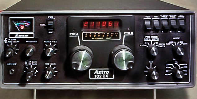
I had an opportunity to use the Astro 102BX a long time ago and was very impressed with it's operation. Here are some of the features I really like about this transceiver:
![]() General Specifications
General Specifications
Frequency Coverage:
PTO Modes of Operation:
Power Input: 12 → 14 VDC negative ground only. No damage will occur over the range of 10 to 15 VDC. 20 Amperes peak current required
Electromagnetic Interference
Reduction:
External Speaker/Phones: ¼" phone jack 4 - 8Ω
External Relay: RCA jack, grounded when keyed
Key:
RCA phono jack
EXT Modulation: RCA phono jack
Fuse:
3 Ampere fast blow
External LO: RCA phono jack
Circuit: Single conversion to 9.00165MHz IF using double balanced mixer for exceptional immunity to overload and cross modulation
Sensitivity: 0.35µV for 10dB S+N/N ratio
Image Rejection:
Better than 60dB
Receiver Selectivity: SSB and CW - 2.4KHz, two 8 pole crystal filter with shape factor of of 1.4:1, 6dB to 100dB (16 pole equivalent)
Passband Tuning: SSB and CW - 8 pole continuously variable highpass or lowpass. LED readout shows approximate audio bandpass
Dynamic Range:
AGC greater than 100dB; third order intercept +5dBm. (IMD products
down 90dB at 40dBm input)
Audio Output Power: Greater than 3 watts into 4Ω
Meter: S units from 1 → 9 and 20, 40, 60 dB over S-9
Circuit Design: Conversion from 9.00165MHz IF. ALC limits SSB peak output power and CW power to 100 watts
Power Input: 235 watts PEP at 13.8 VDC supply
Power Output: 100 watts PEP into 50Ω non-reactive load at 13.8 VDC supply voltage. ALC limits peak power to 100 watts PEP
Unwanted Sideband Rejection: 60dB down at 1000Hz audio frequency
Harmonic Output: 45dB below peak power level
Carrier Suppression: 50dB below peak power level
Transmit Control:
Audio Response: 300 → 3000Hz ±6dB
Meter:
Reads peak power on transmit selected by meter switch; forward power 100 watts full scale, reflected power 10 watts full scale, or ALC
Cooling:
Large capacity heat sink fins supplied. For SSTV, RTTY, and semi continuous transmitting, forced air cooling supplied by a muffin type fan on heat sink fins is required
VSWR Shutdown:
Dimensions:
Power Connect
Antenna Connector: UHF type SO-239
![]() Receiver
Receiver![]() Transmitter
Transmitter
Microphone Input: 47KΩ input impedance
![]() Return to Cubic Mini-Museum
Return to Cubic Mini-Museum
![]() Return to Radio Page
Return to Radio Page
![]() Return to George's Place
Return to George's Place
 ☚
Let's talk about Cubic Radios!
☚
Let's talk about Cubic Radios! ![]()