MY
ROTATOR:
How to modify, repair,
make better a commercial rotator
After I've bought and
repaired an old DAIWA rotator, I've decided I'll not buy a new rotator anymore....only
surplus.
Infact now I've a DAIWA DC7011 and a YAESU G400RC both repaired and now 100% OK
(better than a new one).
I'll describe some modifications (good for all rotator:YAESU G450 G600, KEMPRO..
) to make your rotator better;
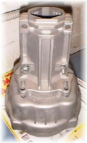
"FINISHING
TOUCH" FOR THE BALL BEARING (See
Fig 1);
the the body of rotator is in cast aluminum and often there are big defects on
the plain; that make attrition to be higher and with the time rotator won't
start;
In my YEASU G400RC there was only small defect but in my DAIWA that was
terrible.
So I worked on it using at first an iron-file ending with a very soft one;
Make the same for the internal aluminum-gear.
INTERNAL SCREW CHANGE (See Fig 2);
The screw that fix the gear system to the body of rotator are not
well-optimized for this use;
On my rotator there is a 2 el. Quad (see my web page) without a
"rotator cage", so there's a little bit stress; with the time the
above screws become slack so that the last gear wasn't really closed to the
rotator body;
often my rotator didn't start: at first it was necesary a simple quick
"left-right-left" with the switch but after months that was not
enought and my rotator started only with the right wind !!
opened the case, i saw the screw become slack, so I've changed it with
better ones.
EXTERNAL SCREW CHANGE : i've used Inox screw with higher head.
CHECK THE MOTOR BRAKE (See Fig 3);
observing the rotator motor when starts moving, you'll see its axle go up
for few mm and after down when stops;
at this point there
is a plastic packing that act as brake; with the time it consume so, if
necessary, change it.
MODIFY THE 500 OHM VARIABLE RESISTOR FOR THE POSITION
REPORT (See fig 4);
in my DAIWA DC7011 control box, after same years, appeared a problem:
turning the beam the meter did't turn with it but moves "step by step";
the problem was the 500 Ohm variable resistor; infact in my Yaesu there was
a wire connecting the central lead to the inside of resitor; in my DAIWA it
was differenter; connecting a wire as above solves the problem (See fig 4).
MOVE THE MOTOR'S CAPACITOR FROM ROTATOR BODY TO CONTROL BOX (See
Fig
5);
while in the YAESU G400 (as in most rotators) the motor capacitor is inside
the control box, in my DAIWA DC7011 it was in the rotator body; that's not
really important but if it goes off, you need to put down the beam, take
down the rotator and change the capacitor;
so I think it's better the capacitor takes place in the control box (See Fig
5).
If the original capacitor goes off, you can use:
- similar-not polarized capacitor:
- make a new one using common electrolityc and two diodes.
CHANGE THE POSITION-DRIVING BELT (See
Fig 6);
It will be not very difficult to find a new belt (O'ring) but in extremis
you can use a common elastic.
ADD A SOCKET TO
IC ON THE PRINTED BOARD (See Fig 7);
on the printed board there are just few transistor an Ic;
It's very useful to add a socket to the IC so you can quickly change and
test it.
FILTERING ALL INPUT/OUTPUT (See Fig 9): the cable that connect the control box to the rotator body is very "long" and acts as an antenna; and you know that RFI are very common in an amateur shack so it's a good idea to filter all the input output of control box using simple ferrite and by-pass capacitor; the picture show a recent modification to a GIOVANNINI ELETTROMECCANICA control box situated in Mike's shack (IK7UFR, OVER OVER) which control cables act as antenna for RF.
CHANGE THE SOCKET O THE CONTROL BOX REAR; that's not really necessary but I think will be better to have the possibility to hard-disconnect the control box - to - rotator cable during storms: lightning arrives not only trought the antenna's cable.
CHANGE THE COLOR (See Fig 8): my DAIWA was pink painted, but I didn't like it: so..that my new !
Follows various projects of rotator and control box:
73 de iz7ath, Talino