RF power amplifiers
This page is under perpetual construction


If you have bug reports or feedback, please feel free to use the email address below.

Low power VHF RF amplifier with VMP1 Mosfet
(IZ1BTS Joe & IK1XPD Max)

We describe the realisation and test of a five watt linear amplifier for the 2 meters band with a VMP1 Mospower FET power transistor from Siliconix (now a brand of Vishay Corp.). The idea comes from an article "Two-meter transverter using power fets" published on Ham Radio September 1976 (pp. 10-15) by WB6BPI, Larry Leighton.
The desirable features of Mos power transistor are Unfortunately Siliconix had discontinued the production of this and similar RF components (VMP-4, Si-8910 Mos quad for DBM) nevertheless we hope this note may be a source of ideas for your next RF amplifier with similar power Mosfet devices like DV-1210, DV-2810....


The electrical circuit (from Ham Radio Sept. '76)

VMP1 was manufactured in a TO-3 case with drain connected to the case.
To heatsink the transistor without adding too much output capacitance I used (like in the original paper) a beryllium-oxide heatsink insulator 1.6 mm thick.
WARNING: precautions must be used working with beryllium-oxide insulators. Pulverized particles are poisonous if breathed.
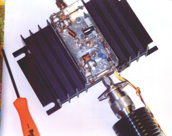
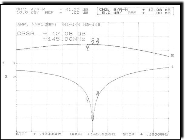
If you select a different kind of insulator you must change the matching networks values.


VMP1 amplifier performances


The amplifier is able to deliver 5 Watt (+37 dBm). The -1 dB compression point is at +39 dBm.
The power supply voltage was +28 V. The quiescient drain current was adjusted to 200 mA; higher drain bias current gives no improvements on IMD test (next).


In this figure you can see the input return loss R.L. or S11 (curve number 1) and the gain S21 (curve number 2) measured with an RF network analyzer.
The gain is about 12 dB and the R.L. is lower than 30 dB in the 2m band.


Two-tone, third order intermodulation measurement set-up.


The spectrum plots here reported shown the input and output signals from VMP1 amplifier.
The Intercept point (IP), with reference to a single-tone output, is IP(dBm)=Pout(dBm)+Pimd(dB)/2 = 47 dBm


The spectrum of the input signal on the VMP1 amplifier (IMD_out) is not perfect. It shows a small third order intermodulation contribution from the previous stage (a CATV amplifier module), 60 dB lower than single tone level. This undesired contribution gives a negligible effect on the measured Intercept Point (IP) level.


IMD considerations
from p.231 of Introduction to Radio Frequency Design, Wes Hayward, W7ZOI, ARRL: "Some large signal VMOS-FETs offer high output intercepts. However, they often require very high bias power to achieve this, perhaps Vdd=25 V and Id= 400 mA. Examination of the low frequency characteristics are initially puzzling, for a curve of Id versus Vgs is extremely linear, lacking in both second and third order curvature. However, the parasitic capacitances are high. Moreover, they are strongly dependent upon the drain voltage, perhaps accounting for the poor intercept efficiencies."


Noise Figure
The amplifier noise figure has been measured with HP8970 and HP346A head without trying to reduce it.
Here the noise figure values versus frequency.

Frequency [MHz] Noise Figure [dB]
139 2.33
140 2.32
141 2.33
142 2.34
143 2.37
144 2.41
145 2.47
146 2.53
Bibliography

Who I am | IZ1BTS homepage | QSL.NET homepage


my e-mail address is [email protected] Last Updated: 28 june 2001