IN3OTD's web site
...under perpetual construction.

Rectangular loop inductance calculations
One-turn loops are often used on the LF band (137kHz) as receiving antennas and sometimes big loops are used also as transmitting antennas. Since it is difficult to make a self-supporting circular loop (the usual shape for receiving loops) with large dimensions, transmitting loops are often of rectangular shape, suspended between two supports.
The inductance of a rectangular loop of sides a and b made with round wire of diameter d (all dimensions in meters) can be computed with the formula found in Terman [1] which says:
L = 0.4 ((a + b) ln(4.0 a b / d) - a ln(a + g) - b ln(b + g)) + 0.4 (2.0 g + d - 2.0 (a + b)) [uH]
where g is the rectangle diagonal (i.e. g = sqrt(a2+b2)); this is the formula implemented in the one-turn rectangular loop inductance calculation form.
A simplified formula was proposed by ON7YD:
L = 0.4 (a + b) (ln((a + b) / d) + 0.692 - 0.35 (a + b)2 / (a b)) [uH]for b/a < 6
and another formula can be derived from the more general formula proposed by Bashenoff [2], which was verified to be valid for almost any loop shape, even with reentrant angles [3], and reported also by Grover [4]:
L = 0.4 (a + b) ln(2.0 a b / (d (a + b))) [uH]
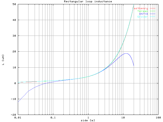
The graph below shows the inductance computed using the Terman formula for rectangular loops with round wire, the ON7YD simplified formula, the general formula found in Grover and with fasthenry simulation. In this example the wire diameter is 5 mm and the length of one side of the rectangle is fixed to 1 m while the other side is varied from 1 cm to 20 m.

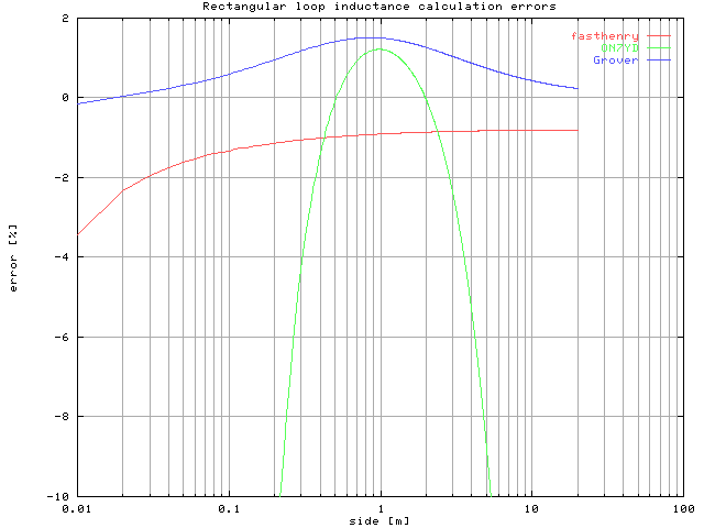
For better clarity the graph below shows the fasthenry, Grover and ON7YD formula error vs. Terman formula for rectangular loop with round wire; as can be seen, the ON7YD simplified formula yield quite good results within its stated limits (i.e. rectangle sides ratio less than 6). The Grover formula yield very good results on the entire range of dimensions considered, as the fasthenry simulation. The error of this latter is probably due to the fact that it can simulate only structures made of rectangular wires, so an "equivalent" square cross-section wire was used instead (see below).

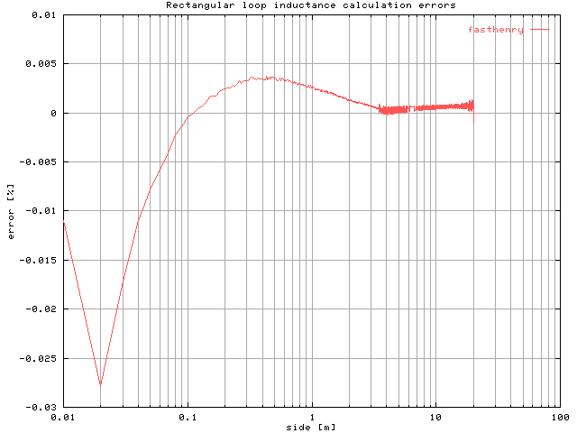
To check the fasthenry results the computed values were compared with the Terman formula for rectangular loop with rectangular wire. The wire cross section is square with a 5.875 mm side and the length of one side of the rectangle is fixed to 1 m while the other side is varied from 1 cm to 20 m.

...note the very good agreement between simulations and the analytical formula.
References: