IN3OTD's web site
...under perpetual construction.

QRP-PA 2008 measurements
I have built the nice QRP HF power amplifier available as a kit at QRP Project (note that the schematic shown there is not the current one, see the kit building instructions). This PA was also used as part of a larger transceiver project, DER SOLF; the whole transceiver and PA description can be found here (in German).
The PA design is quite classic, with a low-power class-A LDMOS driver and a push-pull class-AB LDMOS power stage.
Building the kit was rather easy, the accompanying English documentation is sufficiently well written and, if you can read German, the enclosed German instructions (same as the PDF linked above) are even more detailed.
The most complex part was, at least for me, the "mechanical" side, finding an adequate enclosure and heat sink, drilling holes at the right position and tapping them; I actually spent more time on this than on soldering all the parts... I have used an old PC CPU heat sink I had in my junkbox, but of course that heat sink was designed to be used with a fan (having lot of closely spaced thin fins) so did not perform too well in free air compared to a "classical" heat sink (with a few fins, adequately spaced), so in the end I had to add a small fan to keep the amplifier from overheating, especially when used at higher power.
Here is a picture of the completed PA; note that a proper enclosure is still missing... :

The kit instructions recommends to bias all the three LDMOSs at a quiescent current of 100 mA each, so the first measurements were done at this bias point; results for different quiescent currents will be presented later.
The (small-signal) gain of the amplifier is around 30 dB over the entire HF band, actually slightly below on the 160 m band and still around 27 dB at 50 MHz. Its input matching is not so good, return loss is between 7 dB and 10 dB from 1.8 MHz to 50 MHz and could likely be improved with a little design effort (maybe, one day...)
The data above are summarized in the following picture; all data were measured with -30 dBm at the PA input (i.e. approximately 0 dBm output):
 .
.
For the high-power measurements the output of the amplifier was terminated in a suitable wideband dummy load, so that its output was loaded by a 50 ohm resistance at all frequencies of interest; actual performances when using a low-pass/bandpass filter at the output (which should normally be used if you plan to use the PA "on air") might be slightly different, as the harmonics will not see a pure 50 ohm resistance and the active devices current and voltage waveforms could be somewhat different.
The following picture shows the PA output spectrum when driven with a 10 MHz two-tone signal with 1 kHz spacing between tones, for an output power of 5.6 W PEP (1.4 W per tone):

The (third-order) intermodulation distortion is not exceptional, at -26.4 dBc (i.e. -32.4 dB referred to the PEP output). Later it will be shown that this can be easily improved... in the usual manner, by cranking up the bias current.
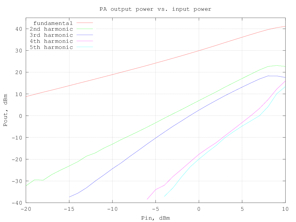
The fundamental and harmonics output levels versus input power, with a 10 MHz sinewave input, is shown in the graph below:
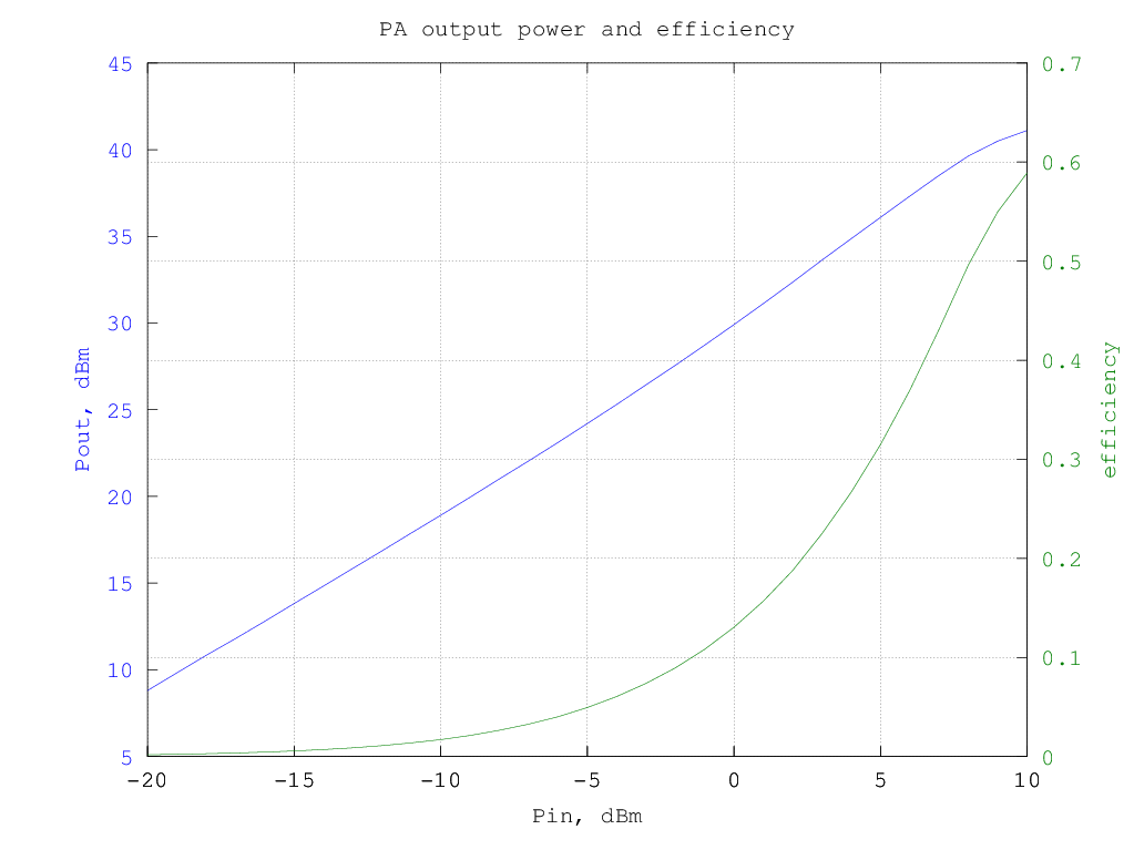
RF output and DC current drawn from the supply versus input power (10 MHz sinewave) are shown in the following graph:

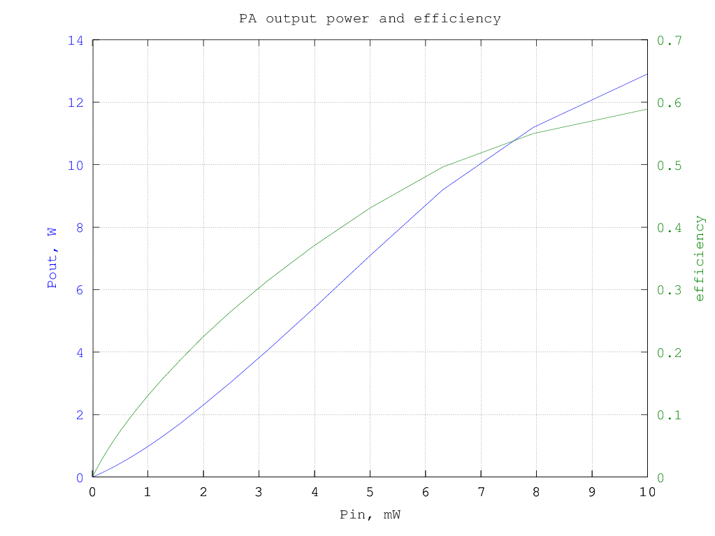
and the resulting efficiency is shown in the graphs below (data are the same for the two graphs, in the first the input and output power are in dBm and in the second they are in watt):
The graph below shows the relative amplitude of the IMD products (separately for upper and lower products) for a two-tone test with varying tone spacing at 5.5 W PEP output:
 the upper and lower IMD tones amplitude are significantly different at large spacing and have a large variation with frequency; this is likely due to interactions between the bias network baseband impedance and thermal effects.
Performances with different quiescent currents
Since the intermodulation performances of the PA, with the recommended bias conditions. are not exceptional I tried several different LDMOS operating points to see if, and by how much, the distortion can be reduced.
Similarly to the graph previously shown, the following picture shows the PA output spectrum when driven with a 10 MHz two-tone signal with 1 kHz spacing between tones, for an output power of 5.6 W PEP (1.4 W per tone); note that the intermodulation products can be significantly reduced by increasing the two class-AB LDMOS bias point current, but there is an optimum point after which the distortion actually increases when increasing the bias current.

The third-order intermodulation products amplitude w.r.t the output power for different bias currents is shown in the graph below (note that the output power is per-tone, so to have the actual [average] power multiply the value by two, to have the PEP, multiply by 4):

Note that the optimum current can be different for different output power levels; in any case increasing the output LDMOS bias current to 150 mA brings already a significant improvement and going to 200 mA for both output devices gives a very good performances over a wide range of power output.