IN3OTD's web site
...under perpetual construction.

Hermes-Lite SDR - TX output measurements
- TX output spectrum
- Harmonics and spurs vs output power
- TX power control
- TxDAC output spurs vs. output DC bias
- TX output spectrum with traps on the TxDAC output
- TX output spectrum with resistive loading on the TxDAC output
- TxDAC output spectrum with filter after the balun
- TxDAC output spectrum with filter partly before the balun
- TxDAC+driver output spectrum with filter partly before the balun
TX output spectrum
As for every amplifier, the Hermes-Lite TX output has also some harmonic components, besides the fundamental but, since the output signal is generated numerically, additional spurious components are present. In general they behave like beat products between the TX DAC sampling frequency and the fundamental, moving up and down the spectrum with the fundamental frequency more or less depending on their order.
While the clock input to the AD9866 has, in this version, a frequency of 73.728 MHz the TX DAC is internally upsampling the signal and using a doubled clock so the aliases involves mainly the 73.728 * 2 = 147.456 MHz frequency.
The following pictures shows the measured output spectrum as a function of the TX frequency programmed in the Hermes-Lite. The X axis is the TX frequency and the Y axis is the corresponding spectrum measured by the spectrum analyzer.
The carrier output power was about 10 dBm and the noise floor of the spectrum analyzer was at around -70 dBm.
Here is the output from the IAMP_N after the matching transformer, without any filtering:

Here is the same spectrum but with 33 pF added in parallel to the TxDAC output (which drives the IAMP):

The capacitor value was chose experimentally to have less than 0.5 dB drop in the fundamental output power at 30 MHz.
To better appreciate the effect of the additional filtering on the TxDAC, here is the difference between the spectra without and with the 33 pF capacitor on the TxDAC output:

As expected, the effect of the added capacitor is greater at higher frequencies but for some reason is affecting more the aliases around the TX DAC frequency than the fundamental harmonics around the same frequency range and there are also some components slightly which have slightly increased.
TX harmonics and spurs vs output power
Here are some graphs showing how some of the TX output spurs and images amplitude changes when the fundamental output amplitude is changed.
ftx=29.0 MHz, fs=73.728 MHz, FPGA FW version 20151018/CVA9/, half-duplex.
The output power can be changed in two ways:
Varying the TX DAC drive
Output amplitude was changed using the "spot level" control routine in Quisk.
Original data file can be downloaded here.


Varying the TX chain gain
Changing the TX drive level, which changes the TX chain (TxDAC+IAMP) gain, see the AD9866 datasheet for details on how the gain control is distributed along the chain.
Original data file can be downloaded here.


The following graphs show the same data as above but with output levels in dBc, i.e. relative to the fundamental output power. Note that the products levels in dBc in general decrease with increasing TxDAC gain (and increase when increasing the IAMP gain ,as expected).


TX power control
The Hermes-Lite output power can be controlled by changing the TxDAC and IAMP gains. The AD9866 can automatically select the stages gain over an overall range of 19.5 dB by using the TXPGA control, as described in the datasheet.
The current FW does not use the TXPGA since it seemed to work incorrectly in the past.
Out of curiosity I have slightly modified it to re-enable the output power control via the TXPGA and it now seems to work fine.
 The TX power control method used seems to have little influence on the output spurs, in particular to the most problematic, occurring at 22.981 MHz when transmitting at 24.895 MHz (ftx) and using a system clock of 73.728 MHz (fs).

Here are the complete data files with the measured levels for the fundamental and spurs/products for the various power levels:
files content is described in more details in the files headers.
TxDAC output spurs vs. output DC bias
...to be added...
TX output spectrum with traps on the TxDAC output
It has been observed that the AD9866 output at the main amplifier (IAMP) is much less clean than from the driver stage (TxDAC) alone. Apparently not all the spurs at the IAMP output are generated by this last stage but some are also due to the loading effect on the TxDAC when this is connected to the IAMP input.
As previously seen, loading the TxDAC output can in some cases produce a cleaner spectrum at the IAMP output.
It has also been reported on the Hermes-Lite mailing list that a series trap placed across the TxDAC differential output could reduce the spur occurring at 22.981 MHz when transmitting at 24.895 MHz significantly, so I did some further measurements with traps.
The graph below show the 22.981 MHz spur level when placing different series-tuned traps across the TxDAC (IOUTP+/-) output. Note that for these measurements the TX output level was not at maximum, but set to obtain 10 dBm output (i.e. the Quisk spot level was 665).

Several kind of traps were tried, but in general it was seen that the spur level decreased when the amplitude of the first TX image at 122.561 MHz was minimized. Interestingly, adding a second trap to reduce the TX image above the DAC sampling frequency, at 172.351 MHz had little effect.
Also, decreasing the first image below a certain level showed only a little improvement on the spur level; likely there are other effects coming into play.
Note also that the spur reduction was lower at higher output levels (13 dBm, Quisk spot level 1000).
The data files used to generate the above graph, including also all the other relevant products/spurs levels can be downloaded here; as usual, the files content is described in more details in the files headers.
TX output spectrum with resistive loading on the TxDAC output
Since after all the previous experiments it was clear that some of the distortion seen at the IAMP output was actually due to some non-linear loading effect on its driver (the TxDAC), I tried to load the TxDAC output in an attempt to swamp out the non-linear load presented to it.
The differential input impedance of the IAMP was previously determined to be about 33 ohm, when set for the maximum gain, so I placed a resistor with this value across the IOUTP+/- pins, effectively reducing the input swing to the IAMP in half. To recover this gain loss I removed the back-termination resistor at the IAMP output, effectively doubling its load and recovering the full swing.
The graph below show the 22.981 MHz spur level (TX frequency at 24.985 MHz) for different configurations:
- the default configuration, with the TxDAC output pins unconnected and a 100 ohm resistor as "back-termination" at the IAMP output
- with the TxDAC output pins loaded by a 33 ohm resistor and the IAMP back-termination resistor removed to recover the full swing
- as the previous point but with in addition a series trap across the TxDAC output, tuned to minimize the 122.561 MHz image level For all these these measurements the TX output level was set at maximum, for an output level of about +13 dBm (i.e. the Quisk spot level was 1000).

as can be seen, the resistive load on the TxDAC reduces the 22.981 MHz spur by more than 10 dB; adding the series trap gives only a little improvement (about 0.5 dB) with this configuration.
There is a little drawback in loading the TxDAC output and it can be seen looking at the TX output power vs. the TX gain:

note that some steps are practically missing, because the TxDAC is now driving a different impedance than the design one.
Data files corresponding to the above graphs, are here, see the file headers for the measurements conditions.
TxDAC output spectrum with filter after the balun
As the TxDAC output power is only about 5 dBm it needs to be amplified by a driver stage before being able to drive a power amplifier. Since its output, while cleaner than the IAMP, has still lot of high-frequency content due to the many aliases, it's good practice to filter out the unwanted components to avoid intermodulation in the following driver stage.
A a 5-pole filter with a bandwidth of about 30 MHz was inserted after the balun used to convert the TxDAC differential output to single-ended. A differential filter placed before the balun could have been used also, but the single-ended implementation seemed more practical, since it avoided to double the number of inductors needed to build a differential filter.
Here is the schematic of the filter:

As shown above, a little tweaking was needed, both in the first capacitor value and in the windings spacings of the toroids, to obtain a nice response:

but when measuring the infamous 2*fs-5*ftx spur amplitude the result was disappointing (measurement for ftx=24.895 MHz):
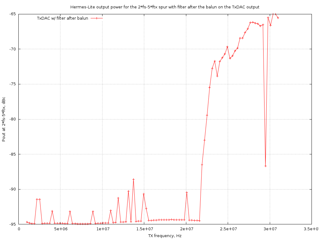
the spur amplitude was 7 to 10 dB higher than without filter!
(Note that the spur falls inside the bandwidth of the low-pass filter only for ftx>22 MHz).
Another experiment was then done to see if keeping the impedance seen by the TxDAC low also at high frequency improved the situation...
TxDAC output spectrum with filter partly before the balun
As said before, it seems wise to have the high-frequency products of the TxDAC terminated into a low impedance. One way is to place the entire (capacitive-input) filter before the balun and so build it in a differential form; of course in this way the number of inductors needs to be doubled.
To avoid this, only the first capacitor was moved before the balun, since in any case only this capacitor will be "seen" at high frequency by the TxDAC output, the others being isolated by the series inductors.
Here is the schematic of the filter used:

Also in this case a little tweaking of the first filter components was needed, since now the balun is placed "inside" the filter and its parasitics modify its response.
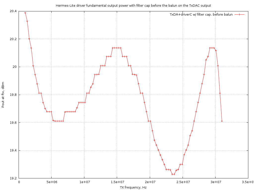
The overall response obtained by moving just the first filter capacitor before the balun is shown in the following graph:

while the measured 2*fs-5*ftx spur amplitude is shown here:
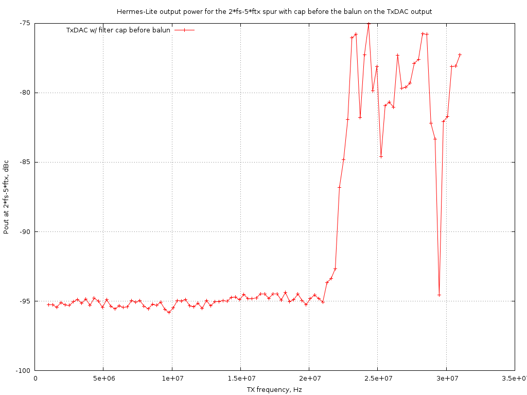
now the spur is reduced to the expected level; the capacitor directly across the TxDAC output had the expected effect.
TxDAC+driver output spectrum with filter partly before the balun
Having obtained a clean spectrum from the TxDAC, with the spurs adequately low and its output low-pass filtered, it's time now to add the driver amplifier to bring the output level to around 20 dBm to be able to drive then the final power amplifier.
The driver amplifier characteristics have been previously measured.
Here is the fundamental output vs frequency of the TxDAC+filter+driver chain:
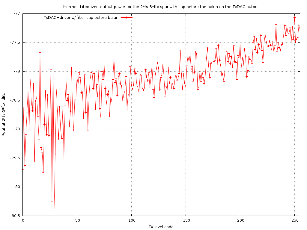
and here is the 2*fs-5*ftx spur amplitude after the entire chain:

the spur amplitude has not been modified by the driver addition, as expected.
Also when changing the TxDAC output power (by changing the TxPGA code) the spurs remains adequately suppressed: