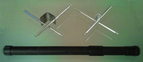
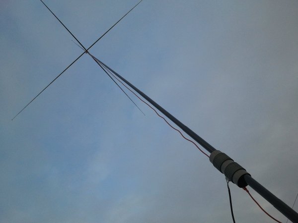
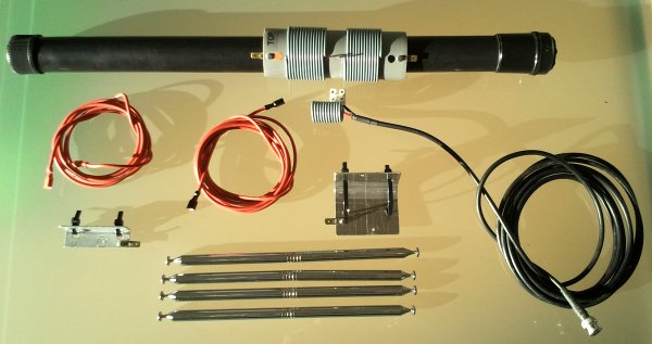
4 telescopic whips per capacity hat, total span 1.9m, mounted crosswise bottom to bottom on
angle brackets of different sizes to fit the pole
Many thanks to Steffen, DL6SFR, for sending me two more links to portable vertical dipoles (see bottom of page).
A load of telescopic whips I bought at a Radio Shack Sale on a recent trip to the US, as well as a 6m / 0.6m fibreglass pole from Lambdahalbe awaited to be used in a project. Unfortunately at the time of writing the telescopic whips are no longer avalable at Radio Shack, but any whip could be used.
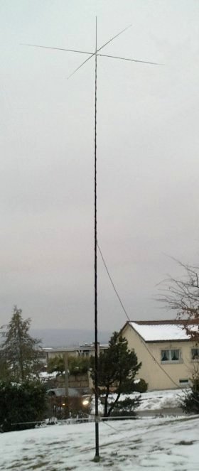
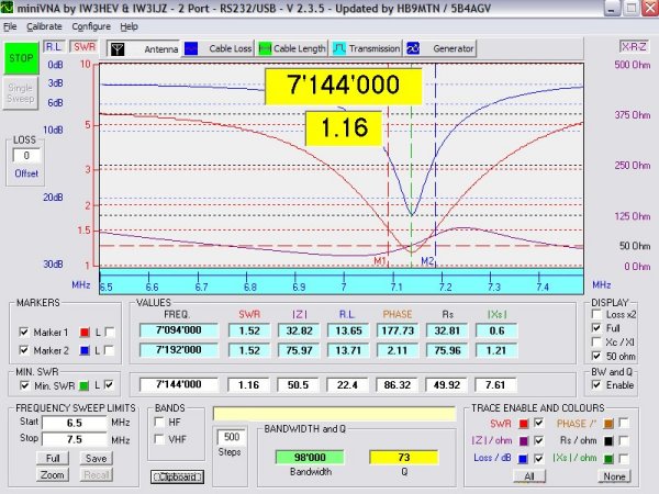
I chose the distance between the two capacity hats for a resonance at 20m without loading coils:
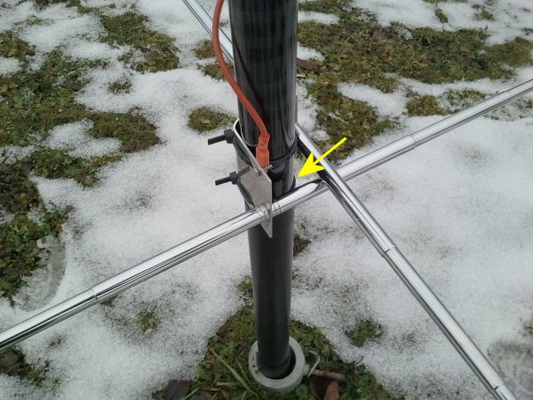
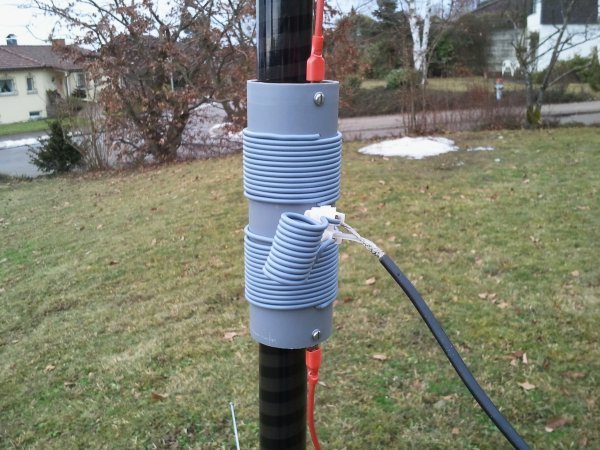
The coax feeder has to be routed as far away from the lower part of the antenna as possible. An angle of 45� ist adequate.
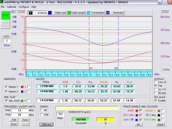
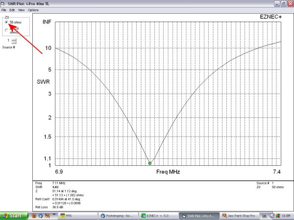
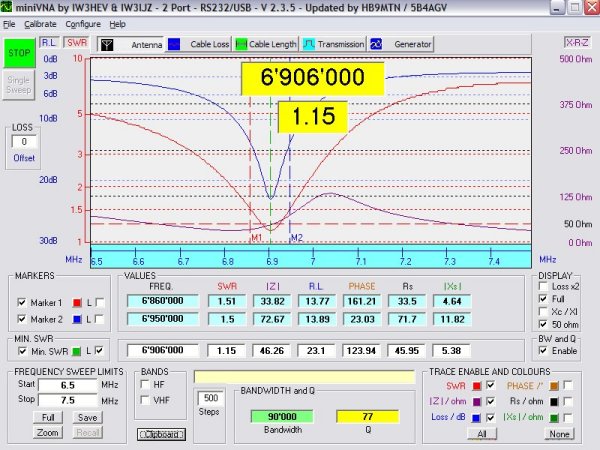
As I mentioned before, my interest was mainly a vertical dipole for 40 m. So I opened my EZNEC 5+ and started to model. The distance between the capacity hats of 4.3 m was given by the 20m resonance. Because of the asymmetric ground load at the lower leg of the antenna, I fed the dipole silightly off center and reduced the inductance of the lower loading coil empirically.
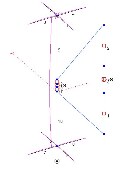
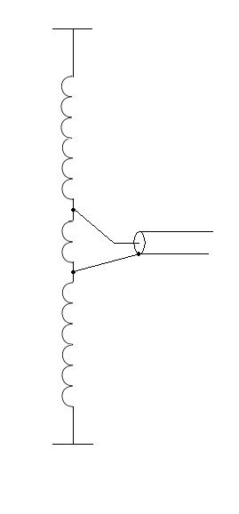
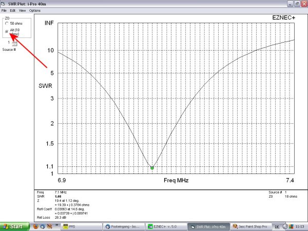
The low impedance can be shifted to the desired 50 Ohms by means of a beta-match, simulated in EZNEC by insertion of a shorted stub (Transmission Line).
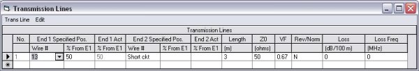
50 Ohm coax has an inductance of about 0.25 uH / m mechanical length, the "transmision line" can be replaced by a coil of 3 m * 0.25 uH / 0.67 VF = 1.12 uH
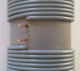
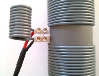
The loading coils were wound on a 50mm PVC tube. 13 and 14 turns of installation wire and the shorted stub from the EZNEC simulation was substituted by an airwound coil across the feedpoint of 11 turns with16 mm inner diameter.
See also my setup for 40m with Buddipole parts
Links by DL6SFR:
Trans World Antennas
Vertical Dipole 10 to 40m
This page is under construction, for more information contact: [email protected]