70MHz SSB Transceiver GW4RWR
Summary
My original intention was to make separate front-end, local oscillator, pre-mix and transmit boards to
equip the FT-225RD
for 70MHz, but it would have been a headache to change bands, there's no quick way to make the '225RD freq counter and PA work on a different band, so I decided on a dedicated homebrew 4m radio. USB/CW modes were required, and the performance should be at least as good as a FT-225RD. Being band-dedicated, it would avoid messing around with an HF radio and transverter with all the cable and switching hassle.
Single conversion to 10.7MHz means that the receive path can be filtered immediately after the first mixer, and subsequent transistors aren't subjected to a whole band full of signals, as they are when a transverter is used in front of an HF radio.
The modules
I have learned the hard way that it's far easier to modify a project if it's split into discreet boards, and the easier each one is to remove, the better. Single boards save space, but this was a one-off; no need for tight spacing - unplanned changes to be expected.
Receiving GB3ANG (Youtube link)
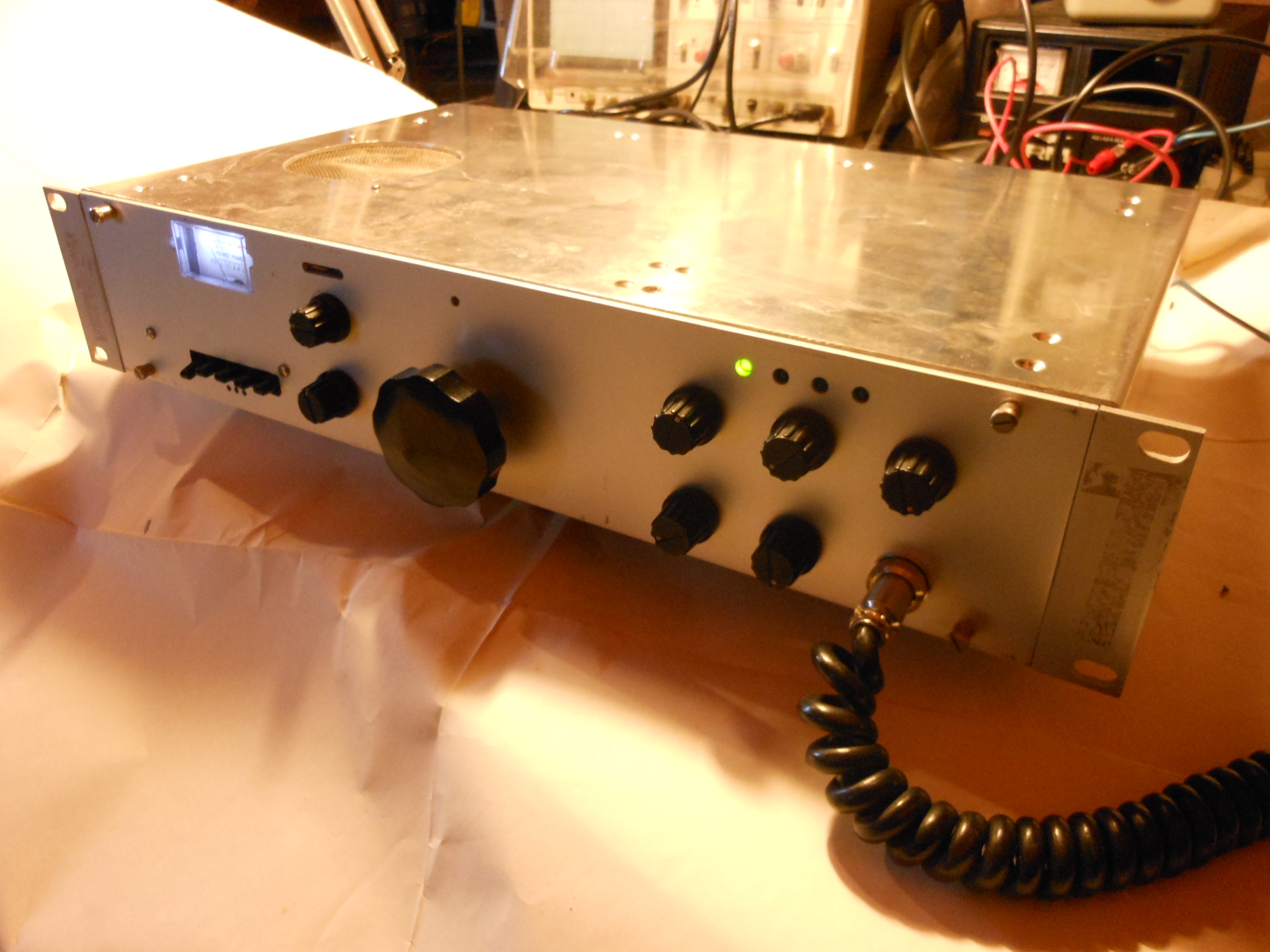
Controls
From left to right, the front panel controls are RIT/OFF/XIT, PA off, External VFO, AGC slow/fast, MOx; knobs for 100kHz bands, LSB/USB/CW/AM, and the big one for the VXO. At the right side, clockwise from top left is Clarifier, IF gain, TX Power, (mic socket), MIC gain, AF gain. I shall try to standardise on this layout on all radios.
The cheap CB meter was chosen since its translucent perspex scale could be backlit; its recessed edges allow it to be pressed against the front panel, without falling through it. The narrow slit to the right of the meter contains nine small LEDs for LM3915-derived relative power indication. Right side panel contains LEDs for RIT, Sequenced PTT out to Amplifier, TX and External VFO.
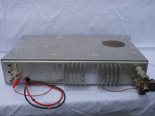
The rear panel has separate Tx/Rx sockets, spaced to mount a CX-520 relay when the radio is operated stand-alone. Alternatively it can be cabled directly to an amplifier with separate tx/rx paths. 'RCA' sockets for AF line-out, ALC in, PTT out to amplifier and +13 out to switch the CX-520. 3.5mm socket for external loudspeaker, larger 1/4" socket for the CW keying line. BNC sockets for external VFO in and Rx IF out.
Conclusion
I should have included a wideband FM option for those days when OIRT is audible. It would be nice to try to know which country it's coming from. But my first crystal filter is 25kHz wide - it needs to either be switched out of circuit, or a parallel unfiltered RF stage added. I also need to retrofit CW sidetone. Have you ever tried to send iambic morse, using the flashing LED power meter as sidetone? Don't.