GM3WOJ ZL1CT - Vintage transceivers page - Let's go Retro !
Updated - August 2009 Best viewed in 1024 x 768
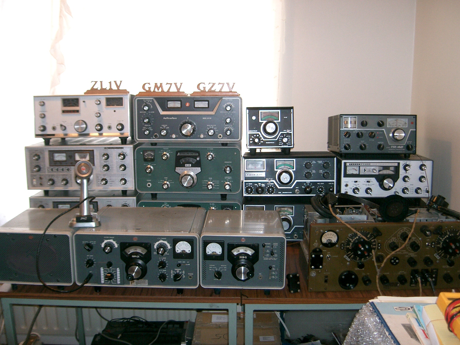
I'm renovating nine 1960's and six early-1970's transceivers, so info will appear here as work progresses. I have good documentation for each and there is a lot of circuit information available on the Internet. Here is a hastily-taken too-dark photo of part of the collection :-
It is great fun bringing an old transceiver back to life or improving its performance. Many of these radios have lain unused for years which often results in more than one fault simultaneously, so lateral thinking is needed when fault-finding. A common fault in old transceivers is that many resistors change value - they almost always go high in value - for example in the NCX-3 a 33kohm screen-supply resistor had changed with age to become 54kohm - the difficult part is deciding what is an acceptable 'range' of values for that resistor which will not degrade the performance of that part of the circuit. As a first step I am repairing the major faults and getting each transceiver to work fully on 1 band, then later I will realign/repair so that all bands are working well.
January 2006 - click HERE for tube/valve info about all these transceivers
These transceivers have a total of 153 tubes/valves inside them - 53 different types are used ! I have 350 spare tubes/valves available !
Collins KWM-2A Serial number 522-1792-000
Specification : 80-10m (200kHz segments), 18 tubes, , transmitter input power 175W PEP on SSB, 160W on CW. Size 14.75 x 14 x 7.75 inches. Weight 18.2 lbs. Original price (August 1963 QST - KWM-2) = US $ 1150 (August 1975 QST KWM-2A = US $1760)
Purchased for £200 in 1998, complete with 516F-2 AC PSU and matching 312B-5 external VFO and Control Unit. This radio works, but there are some problems with trimmer capacitors sticking (a standard fault), so it needs these replaced before it can be properly aligned. It came with dozens of spare valves (e.g. 13 x 6146 PA valves), a spare 70K-2 VFO assembly and a retro silver Turner desk mic. - excellent.

Unfortunately the transformer in the 516F-2 PSU gives secondary voltages which are too high when fed with 230v AC, so I'm having to use an auto-transformer to run the unit on about 200v AC. I've replaced the 'upgrade' solid-state rectifiers with the original valve rectifiers which has helped to reduce the HT voltages to their correct values. Uses a high-impedance microphone and an external loudspeaker, which is contained in the 516F-2 (there is also another loudspeaker in the 312B-5). There is a rare DX-Engineering VOX unit fitted internally.
The most difficult job so far has been repairing the 70K-2 assembly in the 312B-5 external VFO - these VFOs are permeability tuned - the ferrite slug which moves is on a threaded metal shaft and there is a glass (i.e. insulating) ball-bearing at the end of the thread. This VFO dial was only covering about 110kHz of its 200kHz range (again this is a common fault) - the grease used to lubricate the thread dries out and jams the moving ferrite. This repair was fiddly and I had to be very careful reassembling the unit, but it now works well. The Collins dial mechanism is also complicated and needs some 'trial and error' to align the mechanical end-stops with the 'HRO' style dial mechanism and the VFO shaft.
Collins design was remarkably forward-thinking - this radio (approx 1968 vintage) has provision for amplifier switching, split operation, etc. The 312B-5 external control unit has a built-in RF Wattmeter (0-200W and 0-2000W) for use with the transceiver or companion 30L-1 or 30S-1 amplifiers.
This particular KWM-2A has a 'Pacifica Products' badge on the front panel (just visible below the main tuning dial)- a still-trading Hong Kong based company that purchased ex-Vietnam War radio equipment and sold it on to the amateur and commercial markets. Pacifica Products was run by the larger-than-life figure (500lbs = 33stones = 227kg) of Phil F.Wight W5UHK/VS6DR, who died in June 1997 at the age of 57- it's an interesting story that I will relate at length here in due course. It is possible, therefore, that this radio is Vietnam War surplus - all I know for sure was that it was in that part of the world at some stage of its history.
Hallicrafters SR-150 Serial number 415006343030
Specification : 80-10m (500kHz segments), 19 tubes, transmitter input power 150W PEP on SSB, 125W on CW. Size 15 x 13 x 5.5 inches. Weight 17.5 lbs. Original price (May 1963 QST) = US $ 650
Purchased for NZ $200 (£74) in November 2004. This radio works, but still needs a lot of work to make it 100%. The biggest problem is the home-made power supply, which was lethal ! When first switched on, even using a Variac to slowly increase the AC input voltage, a choke nearly melted and one electrolytic capacitor nearly blew up. I've modified and improved it, but the transformer used is unsuitable for producing the +575V DC needed for the 12DQ6B sweep tubes in the P.A.

This radio is well made - the valve VFO is very stable, and by using xtal mixing this stability is transferred to the higher bands. The VFO design is far superior to the KW2000A or KW2000B (simultaneous FM/SSB transceiver!). Construction is solid. VOX (which I hate and never use) is standard, but there is no CW sidetone. Uses a high-impedance microphone, but needs an external loudspeaker. The (I.F. = 1650kHz) crystal filter is 2.7kHz wide, which is too wide for the crowded bands of 2006, but the shape-factor is quite good.
Renovations of this radio are progressing well - it does however use some unusual tubes/valves which are proving difficult to replace e.g. 6T8A ( = EABC80 = 3 diodes in the one envelope) The SR-150 transmitter suffers from a design/manufacturing fault - a missing bypass capacitor on the anode of a cathode follower means it acts as an audio amp instead and contributes ALC voltage on SSB peaks - reducing the peak output to about 50W - this is the mod required to fix this - quoting Don Power K0TNP "On my rig (the only one I have had experience with) the problem turned out to be un-bypassed B+ bus. No bypass shown on the diagram. So maybe at a later date they corrected the problem. Referring to the schematic - the triode section of V-3B is a cathode follower in the balanced modulator. If you follow the plate supply back to its source, there is no audio bypass. This makes V-3B an audio amplifier. And following this audio output, it goes through R-113, supply for the aalc amp. V-5B. and then C-154 and voltage doubler CR-7 and CR-8 and appears as aalc voltage. Reducing the gain of the driver stages. A 1 or 2 mF cap will bypass the plate of V-3B and make it a cathode follower as it was meant. This will allow the aalc circuit to operate normally. The output on voice will be up where it should be" - thanks Don. This radio is now waiting for its PSU to be rebuilt.
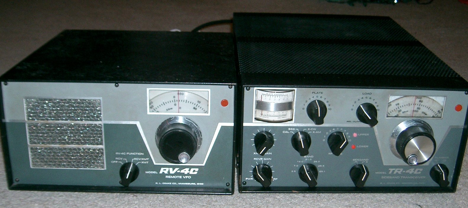
Drake TR-4C Serial number 38445
Specification : 80-10m (600kHz segments), 20 tubes, 5 transistors, transmitter input power 300W PEP on SSB, 260W on CW. Size 10.75 x 14.4 x 5.5 inches. Weight 16 lbs. Original price (August 1975 QST)= US $ 599.95 ($ 699.95 with 34PNB noise blanker)
Purchased for NZ $350 (£140) in September 2005, complete with RV-4C external VFO which includes a loudspeaker and a home-made copy of the AC-4 power supply. The plug-in noise blanker is not fitted. This radio is slightly unusual in that it is 'long and narrow', with controls on the front, rear and sides, and connectors on the side, rear and underneath. The Drake TR-4C is regarded by some as the last and best of the valve SSB transceivers. Late model TR-4Cs were briefly marketed in parallel with its successor the solid-state TR-7 transceiver. See http://www.zerobeat.net/drakelist/drakemod/drmod90.html for more info.
This radio is in reasonable condition, but some of the aluminium cans show slight corrosion. Some of the valves used in the TR-4C are a bit rare. The receiver had a fault - the 'RF Gain' control did not work and there seemed to be no AGC action. This turned out to be a faulty valve - V12 (12BA6) had grid to cathode leakage which was pulling the AGC line down. I've also had to strip down and repair the 'S' meter which stuck at full scale. The permeability-tuned transistorised VFO seems good.
The microphone connector on the TR-4C (and on the Collins KWM-2A) is a stereo connector which looks like a standard 0.25" one, but is 0.2" diameter. Luckily I have 5 spare plugs for the Collins so I have used one of these. I've tested the TX on CW and on SSB - it delivers nearly 150W of RF on 80m, which is fine. I wasted about an hour chasing a 'no output on SSB' problem, before discovering a TR-4C quirk - there is no RF output on SSB if the CW key is plugged in !
February 2006 - another fault developed - the coil of the main changeover relay (K1) went open circuit. This relay has 6 sets of c/o contacts and a 15000 ohm coil, for 110V DC approx. Rather than mail-ordering a replacement relay, I changed the faulty coil for a 7000 ohm coil from a similar 100V relay I had - this involved some very tricky soldering of thin wires, but the end result is good - the TR-4C is back to full working order. I've added a reverse-biased 1N4007 diode across the relay coil to help reduce the chance of a similar failure.
Swan 350C Serial number C 994590
Specification : 80-10m, 14 tubes, 3 transistors, transmitter input power 520W PEP on SSB, 360W on CW. Size 13 x 11 x 5.5 inches. Weight 17.25 lbs. Original price (February 1968 QST) = US $ 420
Purchased for NZ $30 (£11) in April 2005 - in reasonable condition and complete with the original Swan 230-X AC power supply. This transceiver has now been repaired and is working on receive but not very well on transmit - only 100W RF output. Studying the circuit diagram, it becomes obvious that the Swan design is 'cheap and cheerful' - covers 80-10m - using a 5.5MHz xtal filter and band-switched VFO which inevitably will drift, especially on the higher bands. On the top of the VFO compartment are plastic plugs which allow access to trimmer caps for VFO calibration - one for each band 80-10m. Quote from the manual "drift from a cold start will be less than 1kc for the first hour on 80,40,20m and less than 2kc on 10 and 15m" Surprisingly, drift is not too bad in practice - at least on 14MHz- this is an early 2N706 transistor VFO.

There is some surface rust on the PA box, but otherwise the chassis is fine. The PA tubes should be 6LQ6 (6JE5) but have been replaced by type 6B-B14 - an unusual Japanese type (probably identical to the 6LQ6) which I am having trouble finding info. about so far. Uses a high-impedance microphone - has internal loudspeaker fitted. The (I.F. = 5.5MHz) crystal filter is 2.7kHz wide, which is too wide for the crowded bands of 2005 and the shape-factor is not very good (4.6kHz at -60dB)
The construction reminds me of a Heathkit - in fact the manual contains 'Heathkit-like' wiring diagrams for owners to make various additions or modifications ! The 230-X power supply is laughably small for a transceiver which claims power input of 500+ Watts, there are no cooling holes in the PSU metal covers and no fan on the transmitter PA unit. The electrolytic capacitors in the PSU are strange cardboard-covered ones.
The initial fault in the receiver was that C202 was U/S - this is a chassis-mounted can electrolytic capacitor (3 x 30uF 450VW), providing additional smoothing and decoupling - once C202 was replaced (which involved enlarging the mounting hole in the steel chassis which was difficult to cut - using a 1.125" Q-Max cutter) the self-oscillation on receive was cured. After about an hour of testing, a reverse-biased diode started to 'leak' which resulted in the AGC line voltage rising slowly to about -6V, cutting the receiver gain drastically. Replacing the diode cured this second fault and the receiver seems sensitive. It's strange having to peak a signal on receive using the PA grid, tune and load controls ! RF power output is only 100W maximum so far. For some inexplicable reason I like this odd-ball radio !
Yaesu FT-200 (called a 'Tempo One' in the U.S.A.) Serial number 317160
Specification : 80-10m (500kHz segments), 16 tubes,7 transistors , transmitter input power 300W PEP on SSB, 240W on CW. Size 13.25 x 11 x 5.5 inches. Weight 17.5 lbs (8kg) Original price (January 1973 QST) = US $ 319 (+$ 99 for AC/One PSU)
Purchased for NZ $30 (£11) in May 2005, complete with 2 power supplies (one with a label clearly stating - transformer burnt out). This radio worked first time on receive, but does not transmit yet. It's a bit tatty, but you don't expect much for $30. Uses a 9MHz I.F. filter with claimed selectivity of 2.3kHz at -6dB and 4.0kHz at -60dB - note the narrowing of the 'standard' SSB filter bandwidth from 2.7kHz to 2.3kHz as we move into the 1970s. The 7360 beam-deflection tube used as the balanced modulator in this transceiver is renowned for going 'microphonic'. In its day, the FT-200 was actually quite a good radio, despite the low price.

Below is a photo of the underside of the burnt-out original Yaesu FP200 PSU - the case and HV electrolytics have been cleaned up and will be used for the new PSU for the Hallicrafters SR-150. Lucky that this frying transformer did not burn down the previous owner's smoke-filled shack !
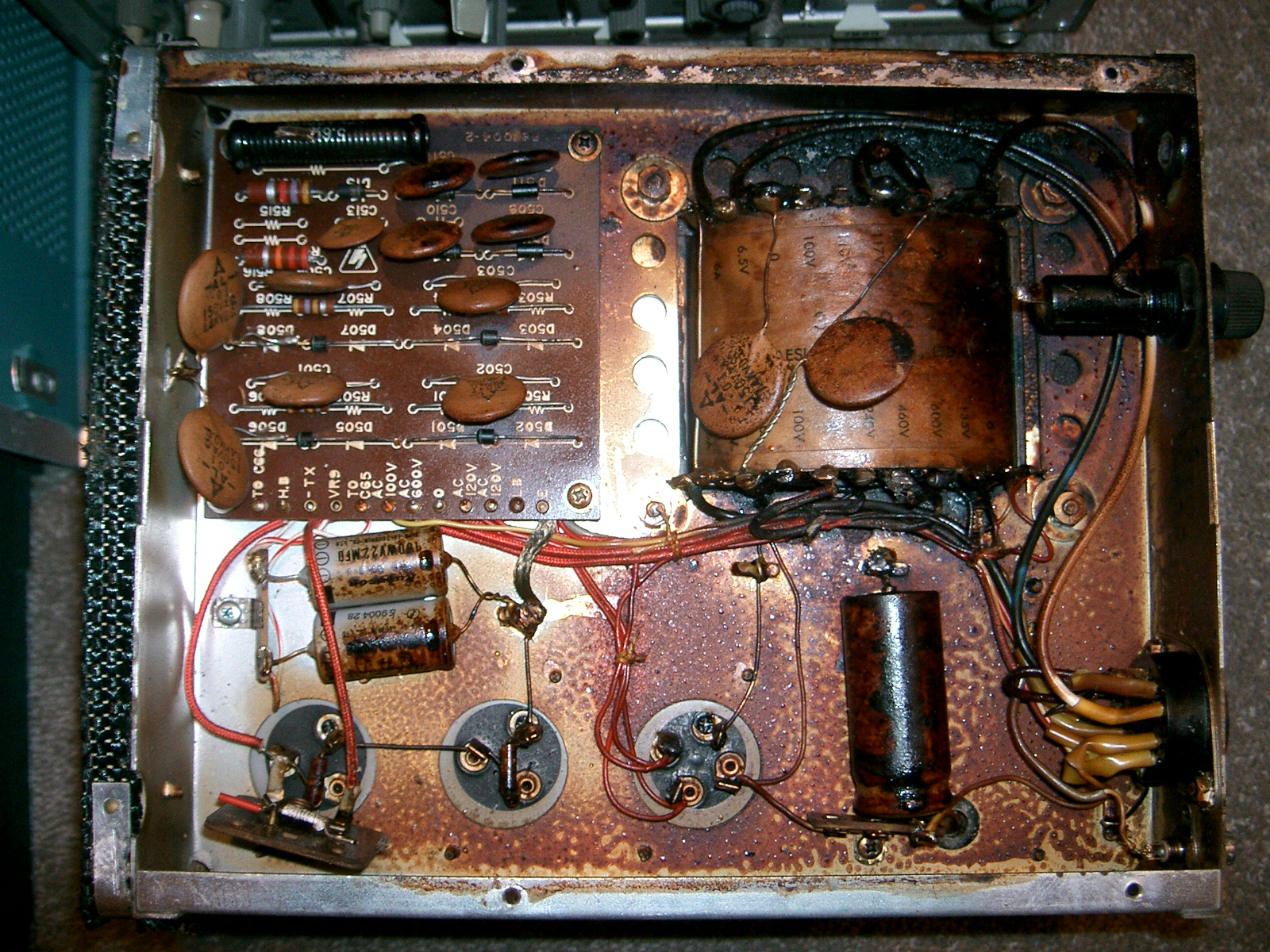
Horrible isn't it ...the tar has melted right out of the transformer, vapourised and coated everything. It was so hot that it desoldered one of the large disc-ceramics you can see on the xfmr. The PSU which replaced it is well-constructed - at first glance it is difficult to tell if this PSU is home-made or a modified commercial product, apart from the 'toilet-roll' insulation on one capacitor (presumably to stop it shorting to the retrofitted smoothing choke). The wiring underneath has all the hallmarks of a commercial unit, but there are too many self-tapping screws - so I think it is a commercial product that has been modified.
I've only played with this radio for an hour - it works well on receive. I only owned an FT-200 briefly, but it was a noticeable step forward from my KW Electronics KW2000, Frontier Electronics FE-600 (worst transceiver ever!) and my somewhat flaky Yaesu FT-dx-560, but that's another story...
Yaesu FT-200 Serial number 3D 336342
Specification : 80-10m (500kHz segments), 16 tubes,7 transistors , transmitter input power 300W PEP on SSB, 240W on CW. Size 13.25 x 11 x 5.5 inches. Weight 17.5 lbs (8kg) Original price (January 1973 QST) = US $ 319 (+$ 99 for AC/One PSU)
Purchased for NZ $120 (£48) in June 2005, complete with FP200 power supply (with built-in loudspeaker) and hand microphone. In much better condition cosmetically than the black FT-200 above, but electrically maybe not in such good condition ? This radio has had some modifications - the PA valves have been replaced by 6146s and the RX RF amp and 2nd IF amp (both 6BZ6) have been replaced by EF183s. The PA mod is a standard sensible mod given the difficulty in obtaining 6JS6Cs, but the reason for the receiver mods is unclear - maybe a modification published in a magazine or on the internet ? I've changed the IF amp (V103) back to a 6BZ6 but left the RF amp (V2) as an EF183/6EH7.

February 2006 - several faults found. The main fault was one of the 6146 PA valves had developed a control grid to screen grid short-circuit, which put +360V onto the -100V rail, making a hot smell and possible other as-yet-undetected damage. It is possible that this 6146 was damaged by a problem with C55 (100pF 1kV wkg) - this crucial capacitor has +360V on 1 side and -100V on the other - the 1kV rating sounds fine until you factor in any additional RF voltage, localised heat etc. - any leakage of C55 is a disaster. I've added a 0.01uF 1kV disc ceramic in series with C55. I don't like the look of the modified neutralising capacitor and there are one or two disconnected wires which I'll need to trace and properly insulate. The 6JS6C screen supply was originally connected to the +165V rail, whereas the 6146s need a higher screen voltage so are now connected to the +360v rail. All the DC voltages are a bit higher than they should be, but unfortunately there are no other taps on the mains transformer. Replacing V102 (12AX7) brought the receiver to life, although the AGC 'hang' time constant seems too short - there is also the characteristic 'popping' sound on speech-peaks of loud SSB signals.
Aligning the trap coils is proving difficult, so there is some extra interference on 40m in the evenings until I can sort this - I'm having some difficulty working out the various frequencies that the coils are designed to 'trap'.
Realigning the driver coils and replacing a soft 12BY7A driver valve means the transmitter is now delivering 120W output on 80,40,20 and 15, and about 70W on 10m. The 6146A P.A. valves (ex Heathkit SB-401e) glow slightly blue, so will need replaced in the longer term. I'm going to use this radio on 80m SSB for further testing.
National NCX-3 Serial number 60 9344
Specification : 80,40,20m only (500kHz segments), 18 tubes , transmitter input power 200W on SSB and CW. Size 13.6 x 11.6 x 6 inches. Weight 25lbs (11.4kg) Original price (July 1964 QST) = US $ 372.80 incl. PSU
Purchased for NZ $50 (£19) in June 2005, complete with NCX-A AC PSU and the XCU-27 100kHz Xtal calibrator unit (which plugs into the rear of the transceiver), the mobile mount and some spare valves. There are also 2 copies of the handbook and the original July 17th 1964 invoice from Ad.Auriema, Inc of 85 Broad Street, New York. The National Radio Co. of Melrose, Massachusetts was famous for the wartime 'HRO' receiver. The first-ever SSB transceiver I saw was an NCX-3 - on the cover of the Dec.1965 'RSGB Bulletin', under the headline 'DXpedition to Agalega'.

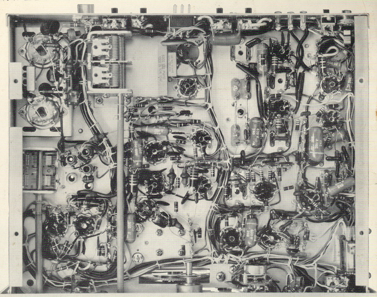
I've only spent a short time so far on this transceiver - it works on receive when powered up, but there is a low gain on TX problem - power output on transmit is only 60W. The multi-core cable from the PSU may have some insulation problems, seeming to have 'aged', but otherwise everything is in surprisingly good condition for a 41-year old radio. The under-chassis wiring (see photo below) is a model of neatness - amazing.

Coincidentally, National featured the same underchassis view (see photo below) of the NCX-3 in their July 1964 QST advert for the radio :-
ZC1 Mk II Serial number 22754
Specification : 2 to 8MHz, 11 tubes. Size 14.75 x 14 x 7.75 inches. Weight 58.5lbs (26.6 kg) Total weight of portable (!) station including spare batteries = 460.5lbs = 209.3 kg
Purchased for NZ $50 (£19) in August 2005, in good working condition complete with original headphones and hand-microphone (Microphone - Hand - no.7) - this is a World War II military HF radio, mostly used by New Zealand forces in the Pacific.
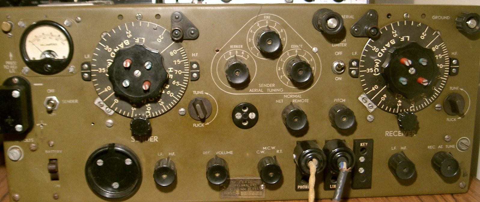
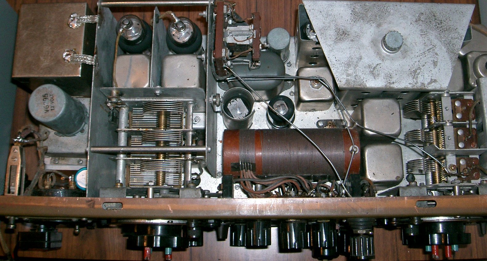
This is a very interesting radio - see the webpage http://www.nzart.org.nz/nzart/history/zc1/ for some historical information. It runs on 12V DC and has a built-in aerial tuning unit.. It covers 2 to 8MHz AM/CW, with RF power output = 1W on a good day. I have the original handbook which contains the circuit diagram and the original metal case with lid. On CW, you can work split and use break-in ! This is one of the stars of my collection of radios ! My aim is to work New Zealand with this ZC1 MkII on 7MHz CW - a tough task. I've tried a couple of times to break in to the UK 'Boatanchor' net on 80m AM, but failed - the operators there don't leave many gaps for unexpected callers, so I gave up. Eventually I'll call in again with a 100W radio, then switch to the ZC1.
October 2008 - this is a new website with lots of useful information about the ZC1 and variants : http://www.zc1-radioclub.wellington.net.nz/index.html
KW Viceroy SSB transmitter Serial number 399 (?)
Received as part of a swap deal in July 2005 - value = zero. Hmmm... a real challenge this one ! Dirty, rusty and unloved - I had to use my angle-grinder to remove the bolts so that I could get the top and bottom covers off ! This 1960's SSB transmitter uses no less than 20 valves - the PA is 2 x 6146 and there are 11 controls to adjust if you change band !
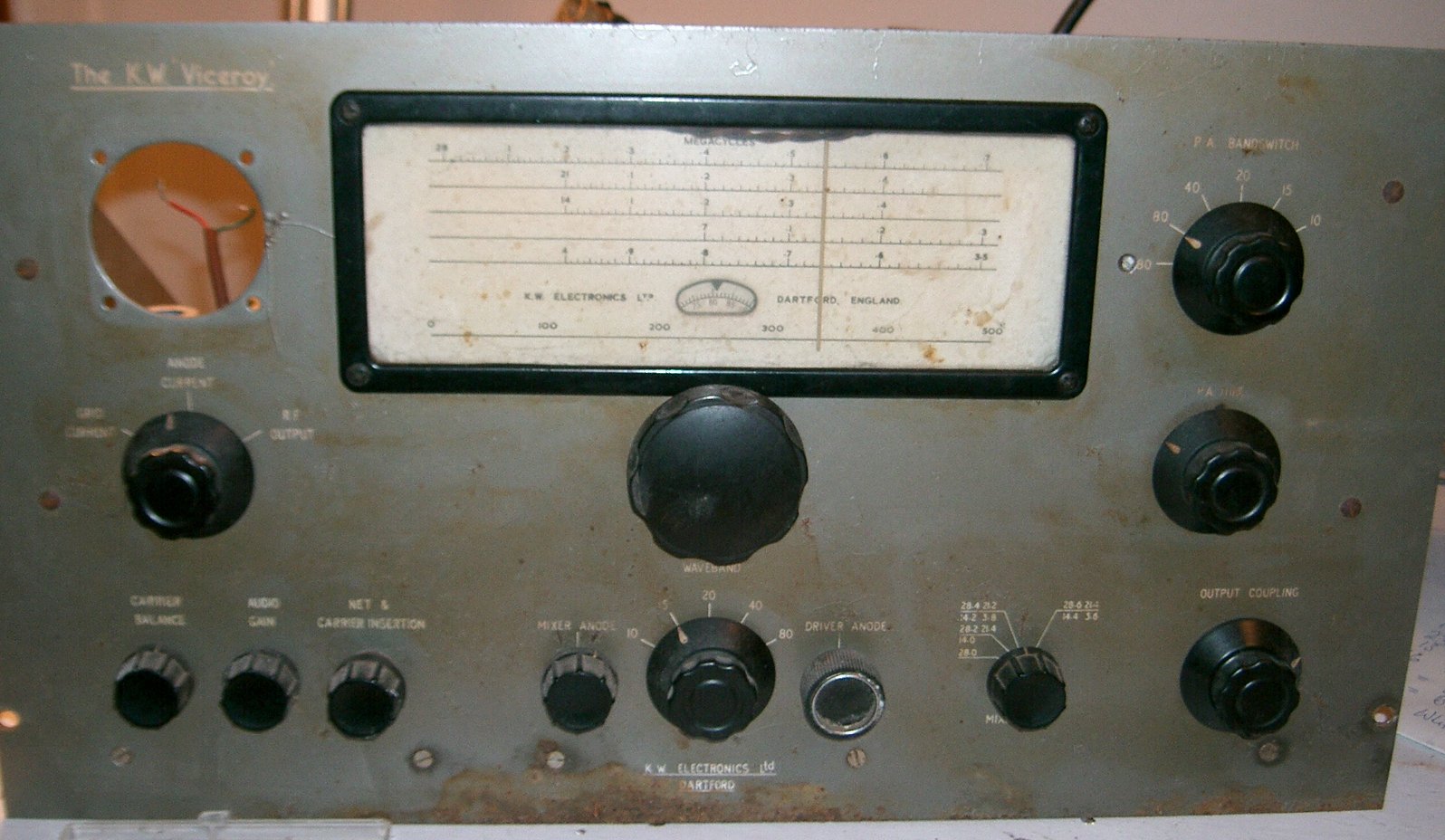
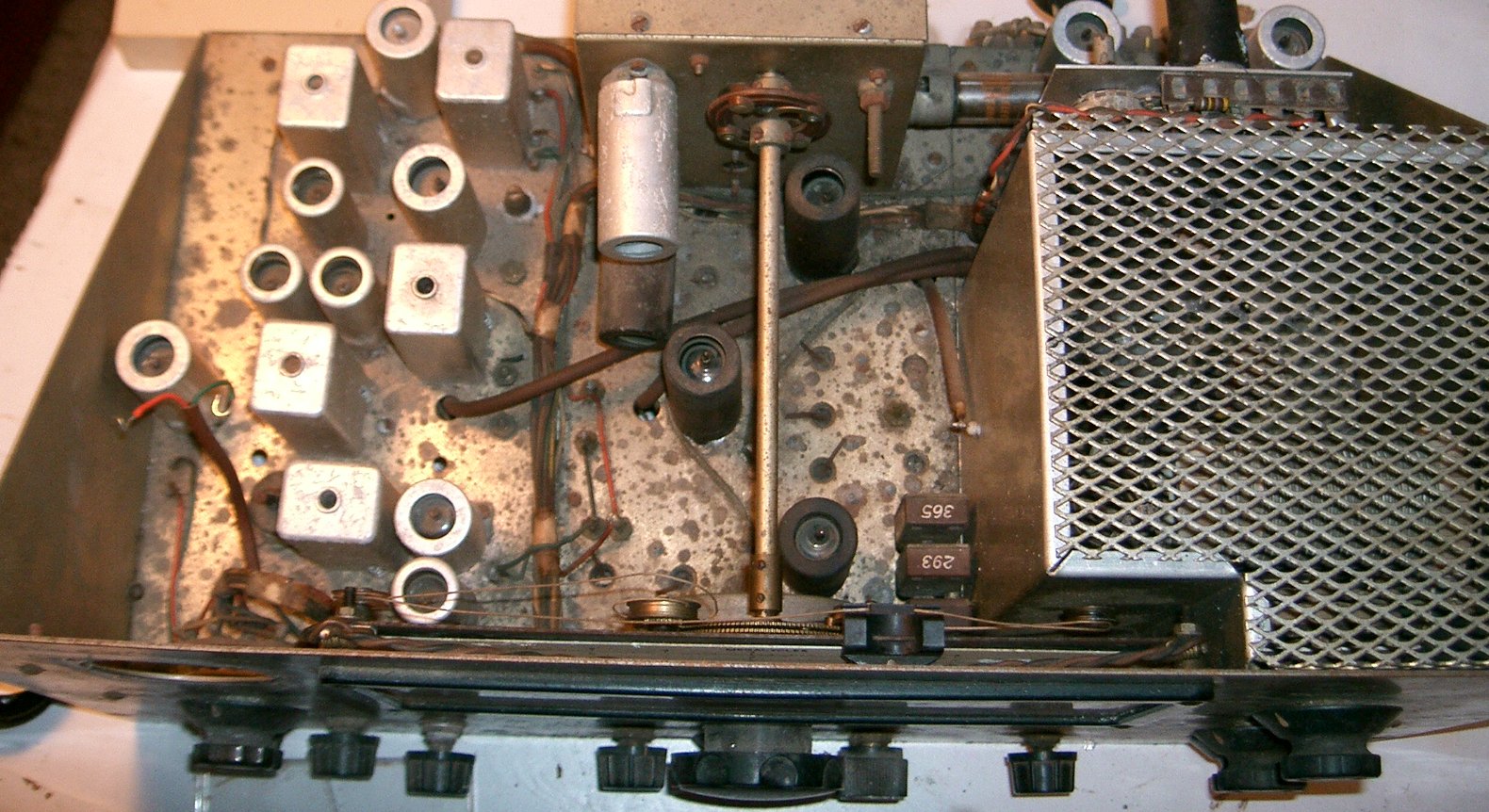
The underside is in fairly good condition, so it can possibly be made to work - if I can find the time and motivation. The photo below of the corroded aluminium scale from the panel meter gives you an idea of the poor condition of this transmitter :
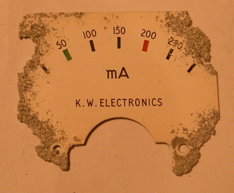 I've stopped this corrosion in its tracks using clear varnish and unbelievably
the meter movement still works after I cleaned out all the aluminium oxide, so I
will use it. The drive cord of the 'Eddystone' tuning dial has broken, but
that is repairable. I have not looked at the separate power supply yet but it
looks in better condition than the transmitter. January 2006 - I've decided to leave the renovation of this KW Viceroy until
later so that I can concentrate on the transceivers. This KW Viceroy is
probably the saddest specimen in my collection to date.
I've stopped this corrosion in its tracks using clear varnish and unbelievably
the meter movement still works after I cleaned out all the aluminium oxide, so I
will use it. The drive cord of the 'Eddystone' tuning dial has broken, but
that is repairable. I have not looked at the separate power supply yet but it
looks in better condition than the transmitter. January 2006 - I've decided to leave the renovation of this KW Viceroy until
later so that I can concentrate on the transceivers. This KW Viceroy is
probably the saddest specimen in my collection to date.
_____________________________________________________________________________________________________________
July 2005 - I've acquired a Swan 350, and made an exchange for a Yaesu FT401b and a Yaesu FT-dx-401.
August 2005 - Brian ZL1AZE gave me Heathkit SB-301e/SB401e separates - thanks Brian !
November 2006 - Alex GD3UMW (GD6IA) gave me a Yaesu FT-One - thanks Alex ! The FT-One is a welcome addition to my collection, but has to be the worst 'high-end' radio of all time - a total turkey in all respects !
June 2007 - I purchased a Yaesu FT-101E
May 2009 - I purchased a Yaesu FT-dx-100 - the original, not the recent FT-100 !!

This lot will keep me busy ! I'm having trouble sourcing enough high-impedance microphones for these radios, but my friend Graham GM3JQJ has presented me with a 'Coronation 1953' microphone which will work with most of these radios - thanks Graham! I've also repaired the Heathkit SB-100 in the photo below for Paul ZL2NS.

