This generic interface can be used for most of the common software, e.g. MultiPSK, DigiPan, Spectrum Laboratory, AGW Packet Engine, etc. I've used it successfully with many modes, from CW to 1200 baud packet.
The first stage is to try out the program on receive. The simplest way is to connect the transceiver loudspeaker or headphone output to the PC mic or line input, adjusting the input level on the PC sound card to give the correct signal level. This will work, but has the following disadvantages:
you can't hear the receiver output
the setting of the receiver volume control is critical.
A better alternative is to use an auxiliary audio output from the transceiver. See below for details of this connection using the FT817/857/897, IC703 and IC706 mk2 transceivers. If you do this, you can adjust the receiver's volume control for a comfortable monitor level, without affecting the signal level going to the PC sound card.
If the received audio fed into the PC is very quiet, then the the programs' decoding performance may be limited by noise (although they will still work OK with strong signals), but if the input signal is at too high a level (generating distortion), then the programs will be unable to decode any signals correctly.
It will be necessary to adjust the microphone silder on the PC soundcard's "Audio Properties" menu, to achieve the correct level. Most soundcards have an extra microphone pre-amp (sometimes labelled "boost"), accessible on the "Advanced" menu: try switching this out if you're having trouble with overloading.
If the program in use has an input level display, you can use the following procedure to set your input level:
Set the receiver to FM mode on a clear channel, and open the squelch - this outputs the maximum noise;
Now set the audio input slider so that the program's an input level display is above half-scale, but never shows overloading.
In order to transmit, a connection must be provided to take the PC sound card audio output into the transceiver's modulating circuitry. It is possible to use the microphone input, but this is usually a very low-level signal, so the PC output needs to be attenuated down, and then becomes more susceptible to noise and interference, leading to possible RF feedback problems.
On the plus side, some transceivers have a VOX facility on their mic input, which may be set up to operate the tx/rx changeover automatically. However, many users have reported difficulty in getting the right audio levels to operate the VOX without distorting the modulation, or finding sounds from the PC triggering the transmitter spuriously.
My preference is to use the external mod. input to the transceiver, and to switch its PTT line from the PC serial port. This removes the need to rely on the VOX control. I can even leave the microphone connected, and go back to using telephony just by operating the mode switch. However, beware that if the PC crashes, the transceiver could end up stuck in transmit!
If your PC only has a USB-type serial port, you'll either need to get an adaptor to the RS232-type, or use the VOX switching method.
In order to be sure that you've got the modulation level into your transceiver set correctly, it will be necessary to get a report from another station, who can observe your signal off-air using his spectrograph or waterfall display: this will show up any distortion or over-wide signals.
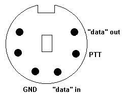
The Yaesu FT817/897/857 transceivers, the Icom IC703 and IC706mk2 and the majority of modern sets use the same 6-pin mini-DIN socket, with the following connections:

Despite the "data" labels, the signals are in fact audio frequency tones.
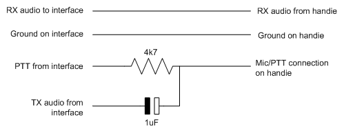
Most modern handie-talkies, apart from Kenwood models use a 2.5mm audio plug for the external microphone and a 3.5mm plug for the external speaker.
The mic audio and PTT functions are combined onto a single pin, so the interface lead needs to separate these thus:

For details of other transceivers, have a look at this page, or consult your user manual.
Using screened lead, connect the receive audio output "data out" to the PC soundcard mic or line input (usually a 3.5mm jack).
Using screened lead, connect the PC soundcard output (often a 3.5mm stereo jack) (make sure you connect to whichever stereo channel has the signal on it!) to the "data in" pin. I included a 22k resistor in series, to reduce the maximum signal level going into the transceiver.
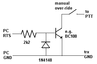
Use the transistor switch circuit shown below to connect the PC serial port to the transceiver PTT.

On a 9-way D-type serial port, the RTS is on pin 7 and GND on pin 5.
On the 25-way D-type connector, the RTS and GND are pins 4 and 7 respectively.
The manual switch is used as an over-ride, to disable the PTT control until the program is running: otherwise if the RTS line is set, the rig will be held in transmit.
If you're using a USB/RS232 adapter, then it may have a lower current output than a dedicated serial port, and it may be necessary to reduce the 2k2 resistor accordingly.
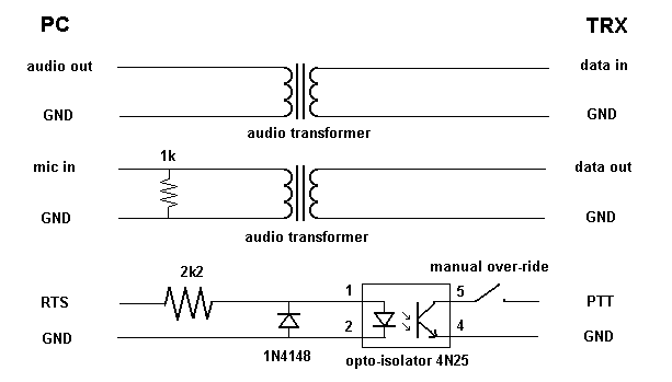
If you're using a desktop PC connected to mains earth, it may be prudent to break the ground connections between the transceiver and computer using audio transformers (e.g. Farnell 1130840, CPC FF01479, Maplin N92CC, or a couple salvaged from old telephone dial-up modems) on the audio lines and an opto-isolator (e.g. 4N25 - Maplin RA57M) on the PTT, instead of the NPN transistor.
This isolated version of the interface will look like this:

I also included a 1k load resistor at the PC mic input, to reduce the signal level - otherwise the volume control slider has to be set right at the bottom.
Some serial ports or USB/RS232 adapters have a lower current output: in these cases, reduce the 2k2 resistor to give sufficient current into the opto-isolator (a value as low as 150 ohms was necessary in one example).
Alternatively, if you find that the opto-isolator cannot sink enough current to operate the radio's PTT, then add an extra transistor to form a Darlington pair current amplifier, as shown in this circuit.
Have a look at this page to see the prototype interface at various stages of construction.
Make sure that any transmit processing or compression, and receiver signal processing functions are disabled, as these will distort the modulation, and make the signal unintelligible.
When using the Yaesu FT817, 857 or 897 transceivers:
To use suppressed-carrier modulation, set the DIG MODE menu to PSK31-U, and select the DIG mode. This is equivalent to applying the tones to the mic input in USB mode. Set the DIG MIC control while observing the ALC meter.
To use frequency modulation of the carrier, set the PKT RATE menu to 1200, and select the PKT mode. This is equivalent to applying the tones to the mic input in FM mode. Set the PKT MIC control while observing the MOD meter.
When using the IC706 mkIIG:
Set menu 29 to 1200bps: this selects the correct pin on the mini-DIN for audio output.
I'll add more information with regard to other transceivers as I receive it.
73 de Ross G6GVI