This page summarises our experiences with rear-panel interfacing of transceivers to computers for digital modes, or to other transceivers for talkthrough applications.
Information regarding squelch operation is not required for a PC datamode interface, just for the talkthrough units.
Model | 
    Connector | 
    Squelch | 
    Notes | 
| Yaesu FT817, 857, 897 FT8100,1500,8900,100D  | 
    6-pin mini-DIN | positive | Drawing more than 1mA from the squelch line mutes received audio | 
| Icom IC2800, E-208 | 6-pin mini-DIN | positive | Note these Icom sets have positive squelch | 
| Kenwood TM241 | 6-pin mini-DIN | positive |   | 
| Kenwood TM-7-series | 6-pin mini-DIN | positive (see note) | The squelch output signal also goes high in TX, 
         so additional DRAT circuitry is needed  | 
| Standard C5900 | 6-pin mini-DIN | positive | Set wanted band on right-hand display.  Tx audio gain is low  | 
| Icom IC706mk2G, IC703 | 6-pin mini-DIN | negative | Set IC706IIG menu 29 to 1200bps: this selects the correct pin on the mini-DIN for audio output | 
| Icom IC706mk1 and 2, IC718 | 13-pin DIN | negative | IC706mk2 has different PTT pins for the two antenna ports | 
| Icom IC735 | 8-pin DIN | negative | Centre pin is not required, so could use 7-pin plug | 
| Kenwood TS2000 | 13-pin DIN | TBD | Different output pins are used for Main and Sub receiver audio | 
The connections on the 6-pin mini-DIN socket are shown below:
Note that a different pin is used for receive audio output for 9600baud packet.
The 8-pin DIN socket used on some Icom HF transceivers is connected as shown: 
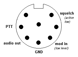
The 13-pin DIN socket used some HF transceivers is connected as detailed below:
Icom IC706 connections | 
    Pin diagram |    
    Kenwood TS2000 connections | 
| pin 2: GND pin 11: MOD (modulation input) pin 12: AF (audio output) pin 13: SQLS (squelch output, active low) pin 3: SEND (ptt input)(only for HF/6m in IC706 mk2!) (pin 7 is a special ptt input for 2m only in IC706mk2)  | 
    ![]()  | 
    pin 3 "MANO" is the (main) receiver AF output, equivalent to the            "data out" pins 4,8 and 12 are Ground pin 9 "PKS" is the PTT line pin 11 "PKD" is the modulation input, equivalent to the "data in".  | 
For details of other transceivers, please consult your user manual.