G4LNA's Home page
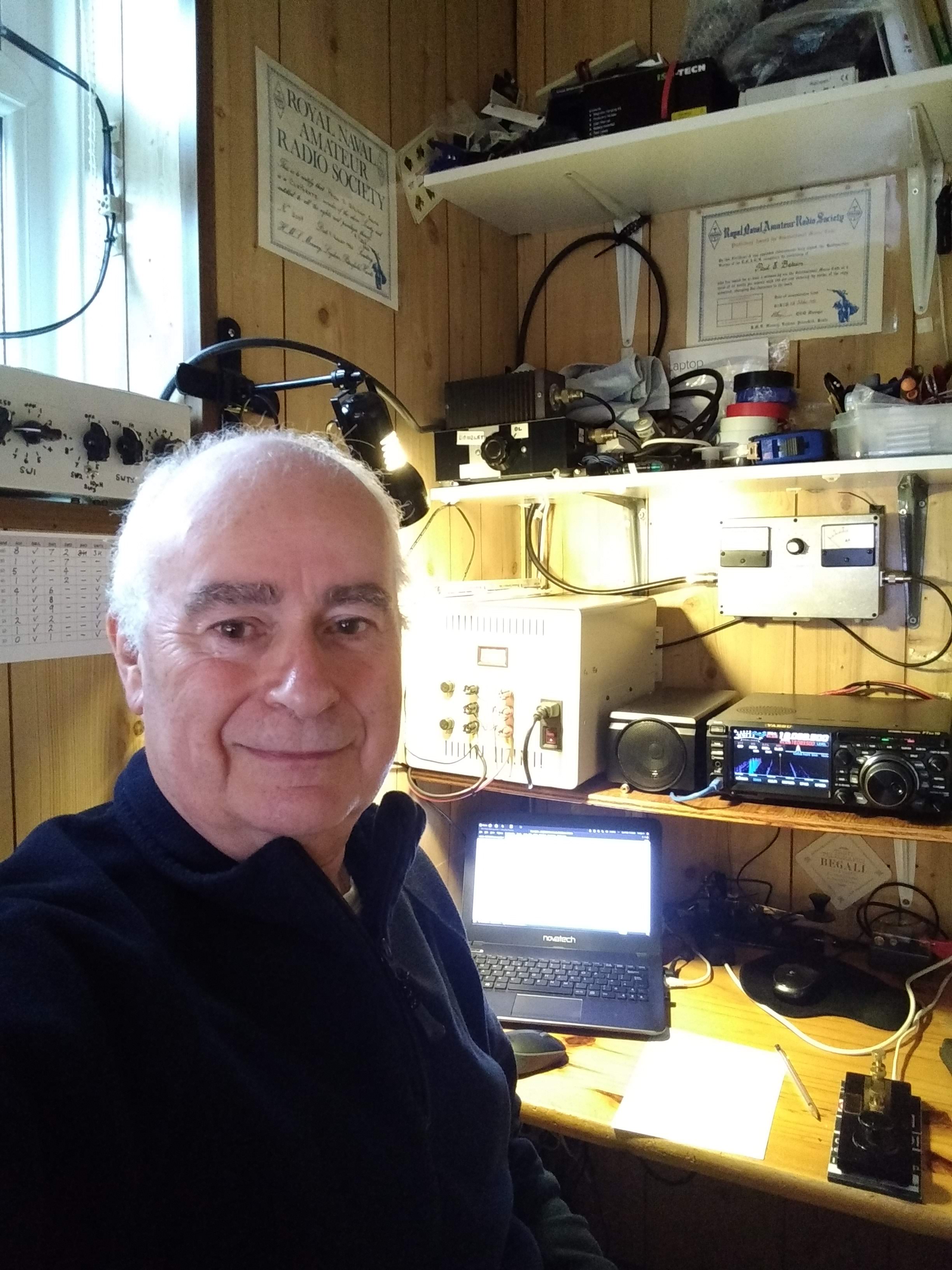
Hello, my name is Paul.
Thank you for visiting my page. I was first licensed in
1970 with a class B callsign, the present callsign
obtained in 1981 after taking my Morse test at the
Marine Services Division in London.
All the links to the circuits are on the left hand side
of this page, I hope that you find something of
interest.
This is the basic QTH information:
Located in the village of Markyate in Hertfordshire,
about 45 km North West from the centre of London.
Post code: AL3 8JS
Locator: IO91ST
WAB: TL01
If you want to email me, my email address is:
 RNARS
2069 RNARS
2069  FISTS
14815 FISTS
14815  SKCC 13264 SKCC 13264
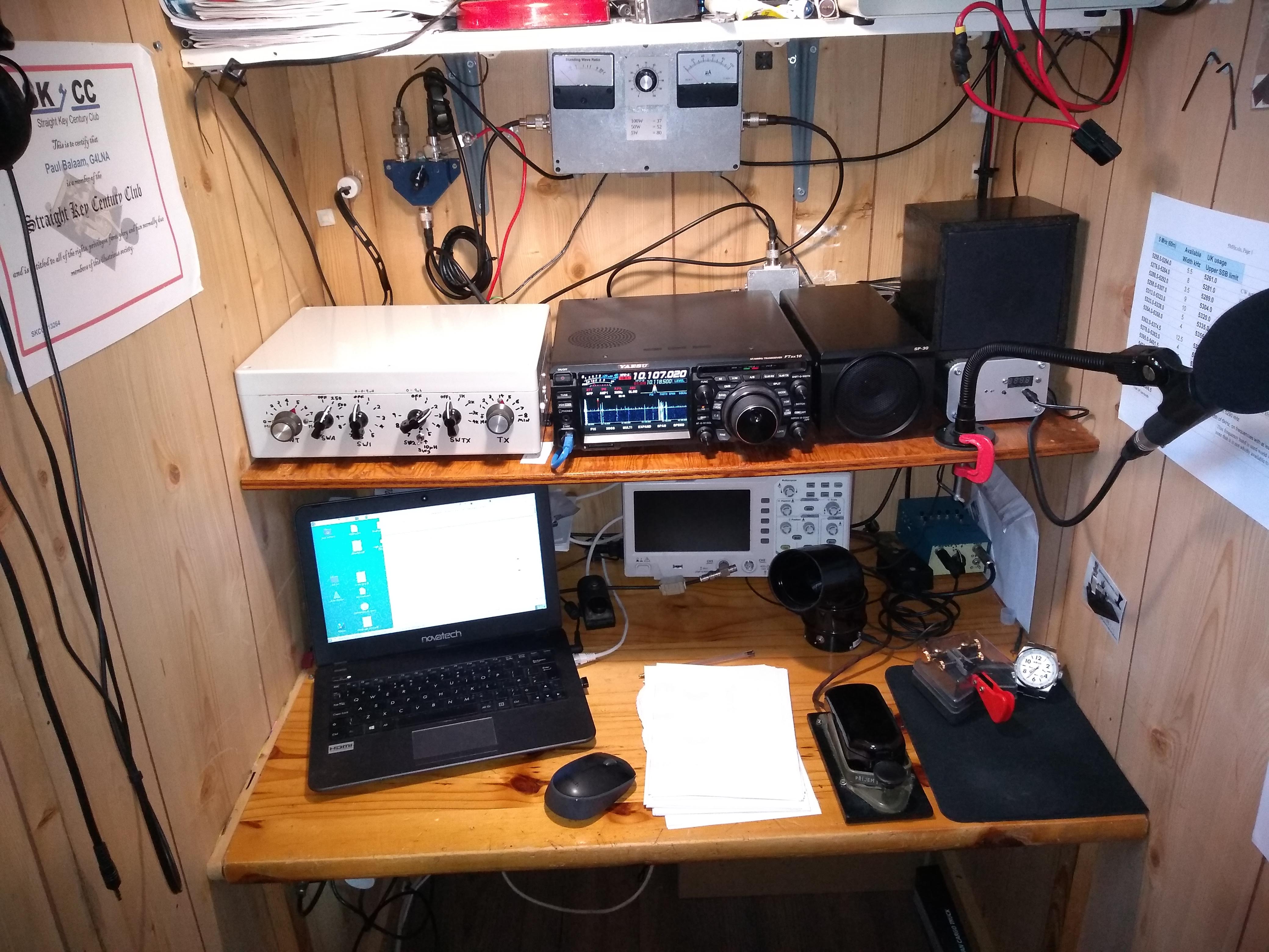
This is a picture of my small shack taken August 2022:
This site is © Copyright Paul Balaam
2017-2023, All Rights Reserved
Free website templates

|