A single bandpass filter will provide selectivity but present the preceding/driving stage with a significant change in impedance between the passband and stopband which can cause significant problems with strong signal handling. One solution is to use two identical bandpass filters terminated by a Quadrature Hybrid transformer at each end. When correctly terminated and adjusted the resulting filter will provide an almost constant impedance to the driving stage both inside and outside the passband. This property is invaluable when used after a balanced mixer using diodes or FETs as switches e.g. the H-
A diplex filter is used immediately after the mixer to provide a wide band termination followed by a quadrature hybrid terminated filter to provide the required selectivity in, for example, a tunable IF application.
See the Mixer Terminations page for a similar application using crystal filters here.
A suggested PCB layout for a single quadrature hybrid terminated band pass filter shown in the circuit below may be downloaded from here. This is a filter with a typical bandwidth of 500KHz for use in the front end or first IF but the technique may also be used with crystal filters which will require matching sections to and from 50 ohms.
Quadrature Hybrid Terminated Bandpass Filter
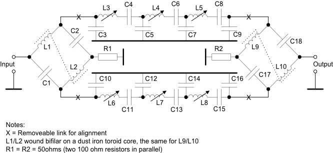
C1 = C2 = C17 = C18. Each capacitor must have a reactance of 100 ohms at the frequency of operation and an allowance must be made for stray capacitances so the final value may be a few percent less than the calculated value.
L1/L2 = L7/L8. Each inductor must have a reactance of 50 ohms at the frequency of operation, e.g. 0.88uH for 9.0MHz.
The bandpass filters should be individually aligned before the overall performance is tested.
The frequency of operation for calculation purposes will be the centre frequency of the band pass filters.