| _._.
_ _._ |
 visitors
since 1999. Best viewed with your
eyes!
visitors
since 1999. Best viewed with your
eyes! |
More
Modifications...
may be found at www.mods.dk.
An extensive database of modification
stuff covering a wide range of
radio brands/models |
|
Rant
I was wondering why Yaesu used
a RJ-45 connector on the FT-900's
microphone. My mic's connector
was recently broken and replacing
the darn thing was a pain in
the butt, particularly the cord's
shield. Luckily, I wasted only
one RJ-45 in the process. |
|
|
|
| RS-232
Rig Interface |
| Shown
here is the schematic of my homebrew
RS-232 interface for rig control using
the MAX232 chip. It is powered by the
serial port and it also comes with a
CW key interface. It fits on a DB-25
shell using a universal PCB. Pins not
shown are unused. The interface is connected
to my FT-900 using a standard PS/2 type
connector (mini-DIN plug) and works
well. For ICOM or Ten-Tec rigs, C10
is omitted and pins 9 and 10 of U1 are
tied. Ferrite beads may also be added
to the input/output pins.
Click here
or on the picture to view a larger image. |
 |
|
|
| Yaesu
FT-900 Noise Blanker Modification |
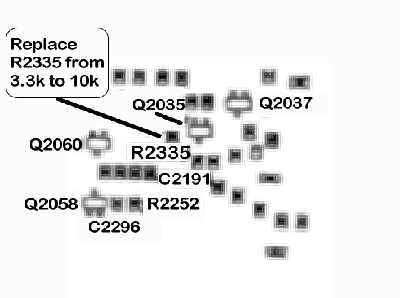
| This
modification improves on the FT-900's
insufficient noise blanker. Replacing
R2335, a chip resistor with a value
of 3.3k, involves removing several cables
on the RF unit to gain access to the
chip side. A value between 6.8k to 10k
is acceptable but some clipping of the
desired signal will be experienced.
I settled for 6.8k in my case and still
have some clipping of strong signals
(s9 and above). I used a standard 1/8
watt resistor in lieu of the chip type.
Be forewarned that the procedure in
gaining access to the RF unit's chip
side is not for the faint-hearted. Good
luck! Click here
or on the picture to view a larger image. |
 |
|
| Amplifier
Interfacing |
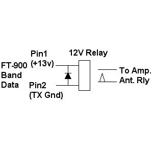
| Here's
a simple linear amplifier interface
circuit that I used to drive a borrowed
Collins 30L-1. I didn't want to use
the rig's internal relay so I used the
Band Data connector's pin 1 (+13v) to
power a 12v relay and connected pin
2 (TX gnd) to the other end of the relay's
coil. The problem with this setup is
the delay introduced by the relay which
caused hot-switching and thus, the missing
1st dot or shortened 1st dash. Click
here
or on the picture to view a larger image. |
 |
|
|
|