If you are devoted to putting the great Collins rigs to work, and unless you are the proud owner of a 312B-5 second VFO, you'll definitely miss an RIT (receiver incremental tuning) control when using the KWM-2 on the air.
If you are not afraid of semiconductors and if you like to have a small construction project, then you can solve the missing RIT problem easily. And the good message is: it can be removed in case you want to have the rig in its original state again.
There have been several proposal on how to apply an RIT circuit to a KWM-2.
The earliest one I could find appeared in CQ in March 1963. Here Nick Taylor, K5YTO, shows a very simple circuit to tune the receiver over a 2.5 kHz range. He simply uses diode CR301 existing in every 70K-2 PTO. Instead of using CR301 as switch with two fixed bias voltages to switch C308 in and out, a variable bias will utilize CR301 as a varicap in series with C308.
The RITEK RIT by John K. Webb, W1ETC, must have been developed in 1992. The circuit board is attached to the back of the PTO case and uses a connection to the top of C308, a point that is identical to the cathode (pin 7) of V301. Probably a varicap is connected to this point.
That's it - there are really no secrets on how to build an RIT. Some varicap must be added to the PTO and made operational when RIT is wanted and the TRX is in receive mode. A variable bias is needed for the varicap and a switch to switch the RIT in and out.
Numerous solutions can be thought of - so you have to choose your own.
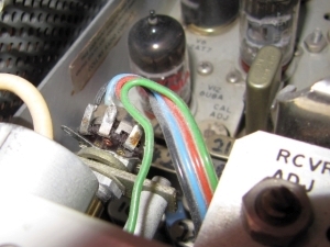
I had to open the PTO anyhow as it needed some new lubrication. That was the chance to add a few items within the PTO and to route a further wire through the PTO wire harness. For details please consult the circuit diagram.
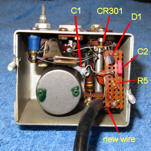
And my KWM-2 had a defective Waters rejection module. That had to move out and the tuning capacitor that was mounted concentric with the ON/OFF switch was replaced with a potentiometer for the variable bias voltage. As there is no noise blanker installed, the NB switch position can be used as RIT-ON. That even ensures that in CAL mode the RIT is always off.
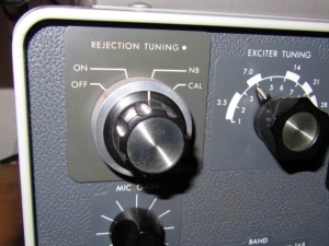
Here you can see the concentric former rejection tuning and power switch, and the RIT potentiometer mounted on the bracket that formerly held the variable capacitor.
Of course, potentiometer and switch can be put anywhere, even outside in a small box. Then probably shielded wire connections should be used. And the varicap does not have to be inside the PTO. It can be placed outside the PTO box with the series connected condensor contacting the top of C308 (like done by the RITEK kit) or wrapped around pin 7 of V301.
The circuit adds capacitance to the PTO circuit and thereby lowers its frequency by about 2 kHz. Therefore the PTO has to get a new alignment after RIT installation.
Here now is the circuit diagram.
Actually, this is very simple: a varicap and 3 new parts within the PTO, a stabilized supply for about 20 V, fed from the TR275V rail, and a supply for the small relay, fed from the filament circuit. Then the small SPST relay that is driven by a logical AND. It is only energized when the ON/OFF switch is in NB position and when the R275V rail is on, i. e. in receive mode.
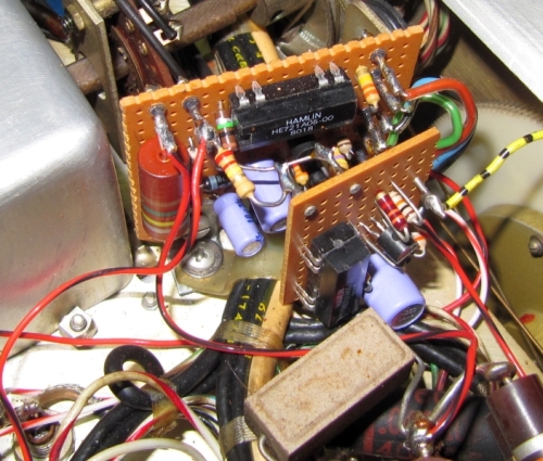
All this can be put on a small circuit board under the chassis, with four connections to J17, the EXT VFO POWER socket, and one connection to J24, the NB POWER socket. And of course, one connection to the varicap circuit. The board is held in place by a small metal angle under the screw that holds the wiring harness.
Actually, above you can see two boards. The one behind has the RIT components, and the one in front adds another function for CW: in transmit mode only, the PTO is shifted by the difference between the built-in sidetone frequency and the desired 800 Hz. That makes it possible to tune CW reception to 800 Hz and to be right on that frequency when transmitting.
It works, but I cannot really recommend it. The KWM-2 has not been designed for CW, and its signal generation via sidetone and SSB modulation is not the best possible. A good adaptation of the KWM-2 to CW has still to come. At least, you can have a look at my circuit diagram for this augmentation of the RIT circuit.
So you can see how easy it is to build an RIT control for your KWM-2. And, please don't hesitate to ask questions in case I left anything untold.